There’s a category of machining problem that looks simple on the surface: rotate a part to a new angular position, hold it there precisely, machine it, then rotate again. Repeat a few hundred thousand times. The mechanical system responsible for that sequence — the rotary indexing table mechanism — is deceptively straightforward to describe and genuinely demanding to build well.
The word “indexing” is doing a lot of work here. It doesn’t just mean rotation. It means controlled, repeatable, locked rotation — the kind where the position at step 47 of a production run is identical to step 1, and still identical after six months of continuous use. That’s what separates a rotary indexing table from a general-purpose rotary table, and it’s what makes the internal mechanism the defining factor in whether the system performs.
This article breaks down how a rotary indexing table mechanism works, what distinguishes the main mechanical types, and what the design choices mean for production environments.
Rotary Indexing Table Mechanism — What Indexing Actually Requires
Before getting into drive types, it’s worth being precise about what the mechanism has to accomplish. An indexing cycle has three distinct phases, and each makes different mechanical demands:
Phase 1 — Rotation: The table accelerates from rest, rotates through the required angle, and decelerates to a stop at the next position. The mechanism must transmit enough torque to move the table and its load (workpiece plus fixture) through the required angular velocity profile within the cycle time the process demands.
Phase 2 — Locking: Once at position, the table must be mechanically locked — not servo-held, mechanically locked — against the cutting forces, clamping forces, and vibration that the machining operation generates. A servo drive holding position through a backlash-prone gear train is not locking. A hydraulic or pneumatic clamp engaging a hardened seat is locking.
Phase 3 — Positioning accuracy and repeatability: The locked position must be accurate (close to the commanded angle) and repeatable (the same every time). For a 12-station indexing table, that means 30° increments that land within arcseconds of their nominal value, every cycle, indefinitely.
A rotary indexing table mechanism that handles all three phases well under production conditions is a precision mechanical system regardless of how simple the concept sounds.
Rotary Indexing Table Mechanism Types — The Four Main Designs
1. Cam-Driven (Roller Gear Cam / Barrel Cam)
The cam-driven indexing table is the traditional workhorse of high-speed production indexing. A precision-machined barrel cam or globoidal cam rotates continuously, driven by a motor. Its profiled surface engages a set of rollers mounted on the table rim. As the cam rotates, the roller engagement geometry drives the table through a precisely controlled motion profile — acceleration, constant velocity (if any), deceleration — and then dwells while the cam surface holds the rollers stationary.
The motion profile is determined entirely by the cam geometry and cannot be changed without a new cam. This is both the strength and the limitation of the design. The strength: the motion is mechanically guaranteed, smooth, and consistent regardless of servo tuning or control system variation. The limitation: changing the number of stations, the dwell angle, or the motion profile requires a new cam — a significant cost.
Cam-driven indexing tables achieve very high cycle rates (some designs exceed 400 cycles per minute for small-diameter tables) with excellent positioning repeatability, because the cam profile directly controls the kinematics without any intermediate gear backlash. They are the standard choice for high-volume production lines where speed and repeatability are paramount and the station count is fixed.
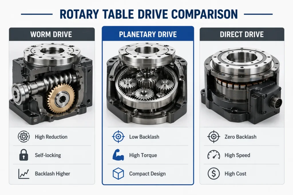
2. Worm Gear Indexing
A worm and worm gear arrangement drives the table through a high-ratio reduction. The motor drives the worm; the worm gear, integral with the table, reduces speed and multiplies torque. A separate hydraulic or pneumatic brake clamps the table at each indexed position.
Worm gear indexing tables are flexible — the number of stations and the dwell time are programmable — and the self-locking geometry of the worm drive provides inherent resistance to back-driving even without the clamp engaged. Backlash is the main precision limitation. Standard worm drives have 15–30 arcseconds of backlash; preloaded dual-lead worm designs bring this to 5 arcseconds or less for precision grades.
This is a well-understood, cost-effective design for moderate-speed indexing with variable station configurations. The worm gear’s inherent sliding contact means higher friction losses and more heat generation than rolling-contact alternatives under continuous high-speed duty.
3. Mechanical Rotary Indexing Table — Hirth Coupling
A Hirth coupling (also called a serrated or curvic coupling) is a precision face-spline arrangement. Two matching toothed rings, one on the table and one on the base, engage when the table descends axially onto the base. The tooth geometry self-centres the table to its angular position with accuracy determined by the tooth form precision — typically 1–3 arcseconds for quality Hirth couplings.
The mechanical rotary indexing table with Hirth coupling separates positioning from rotation entirely. The table lifts off the base to rotate (driven by a simple motor and gear), then lowers to engage the coupling for machining. Position accuracy comes from the coupling geometry, not the drive train — which means drive train backlash is irrelevant to final position accuracy.
This design achieves the highest positioning accuracy of any indexing mechanism at reasonable cost, and the coupling wear is extremely low because the teeth only engage under the load of the clamp, not during rotation. The limitation is the lift-and-lower cycle, which adds mechanical complexity and limits the minimum cycle time compared to cam-driven designs.
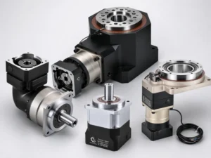
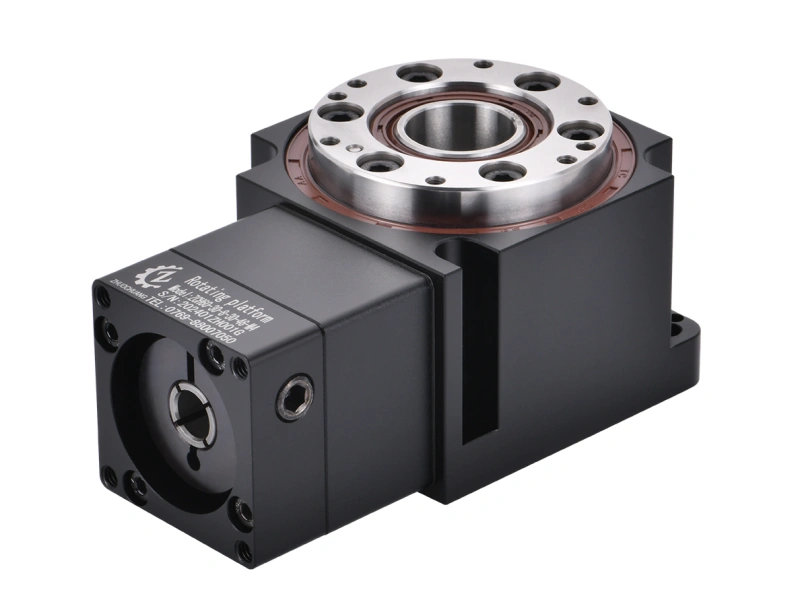
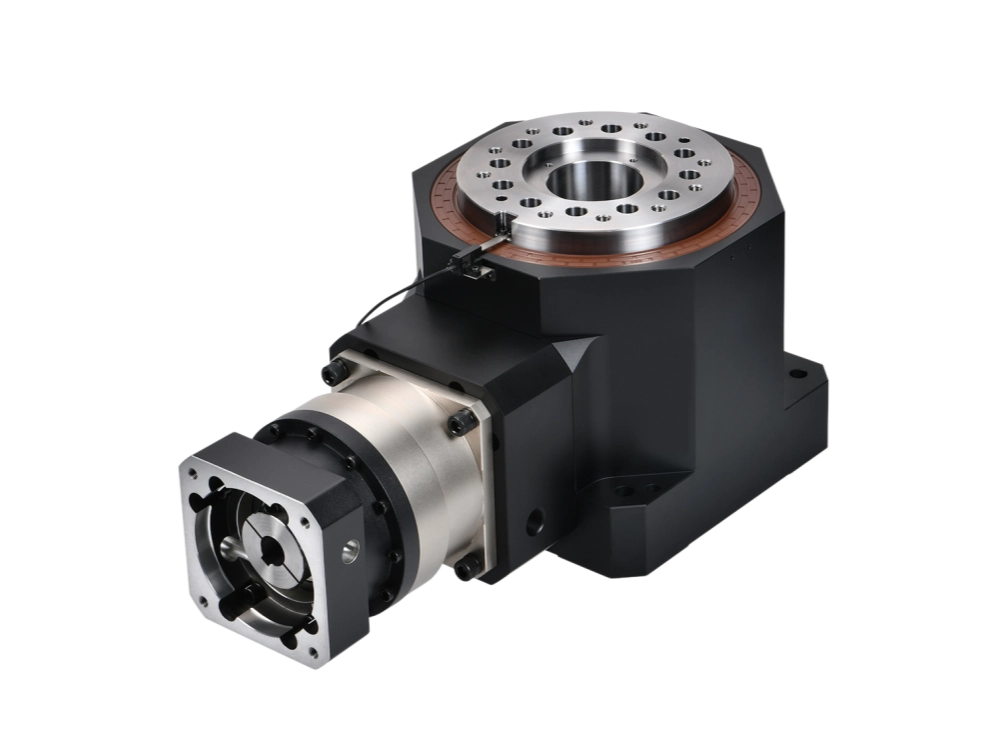
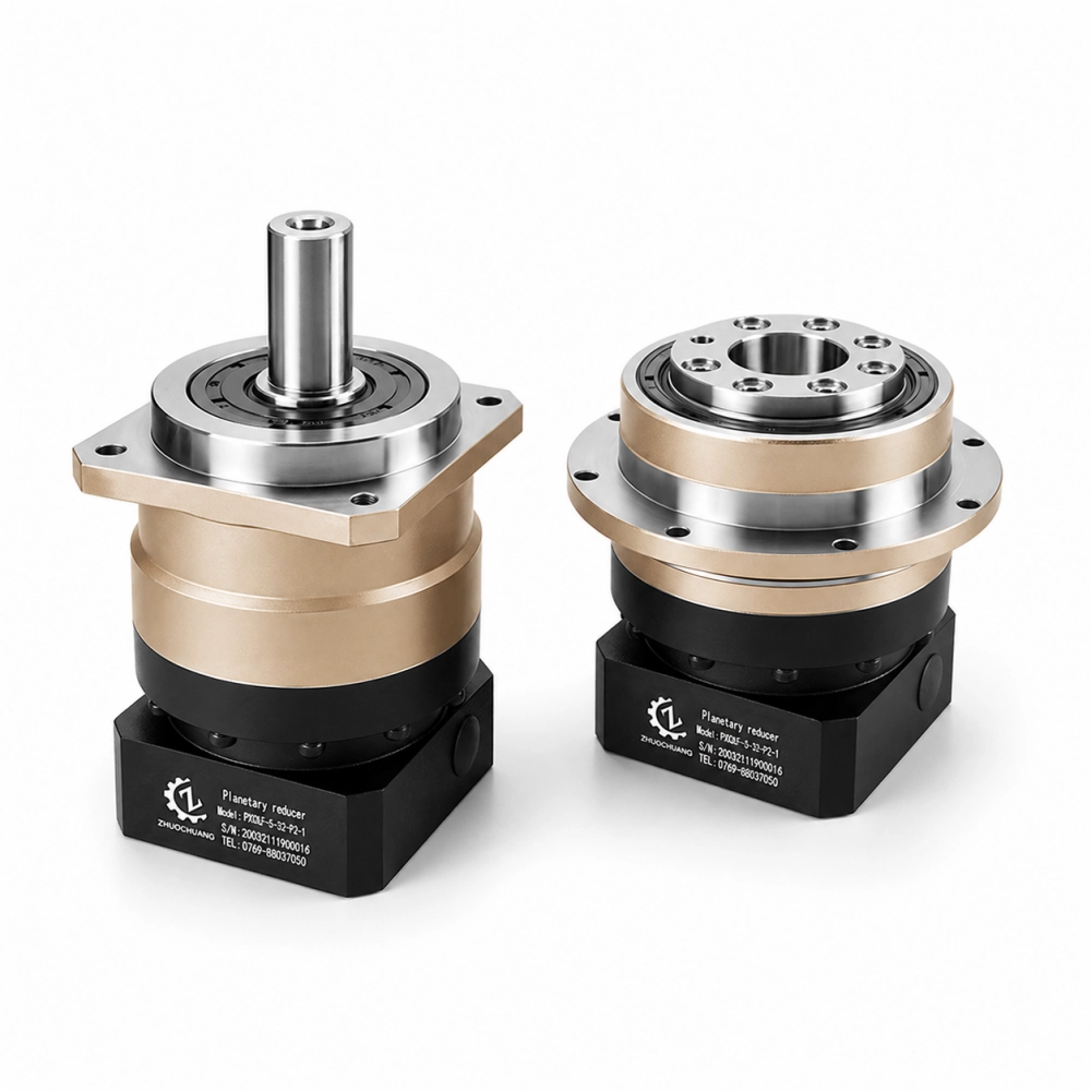
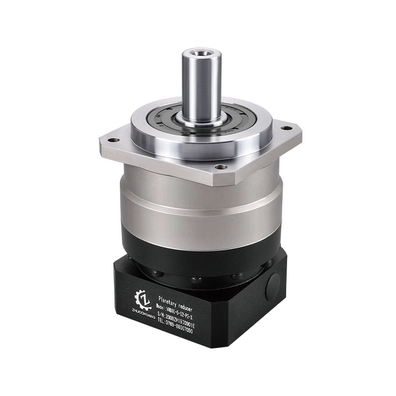
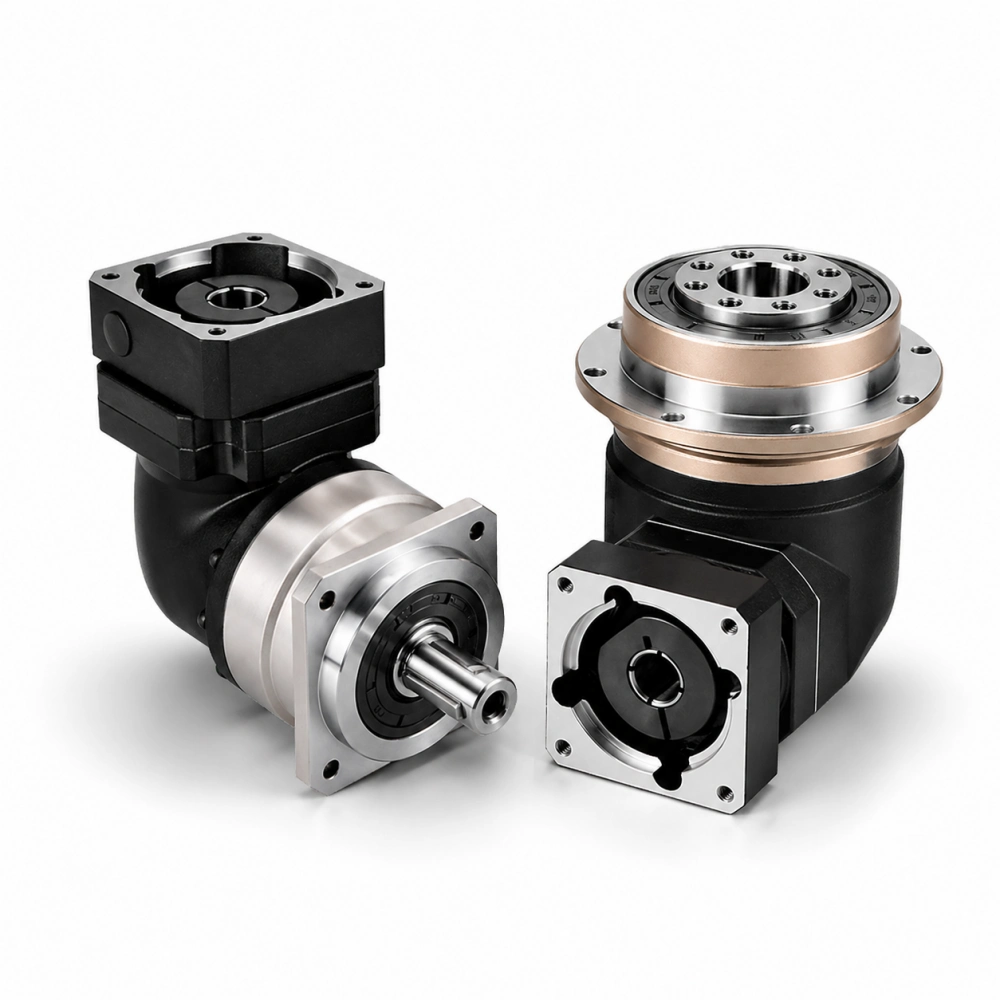
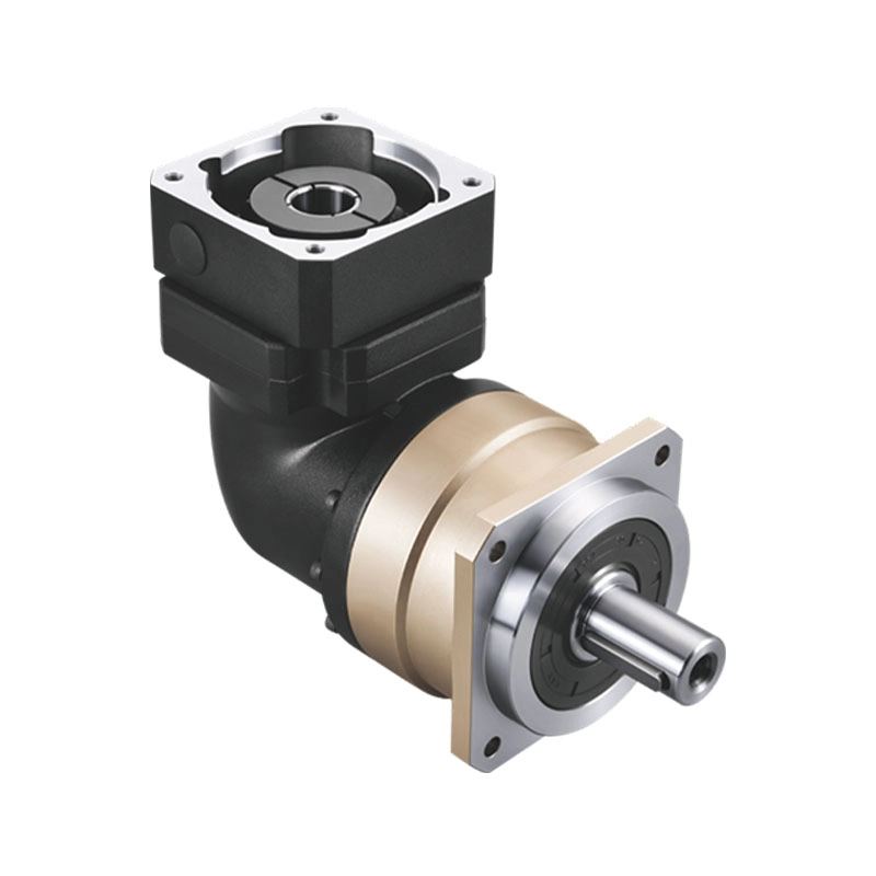
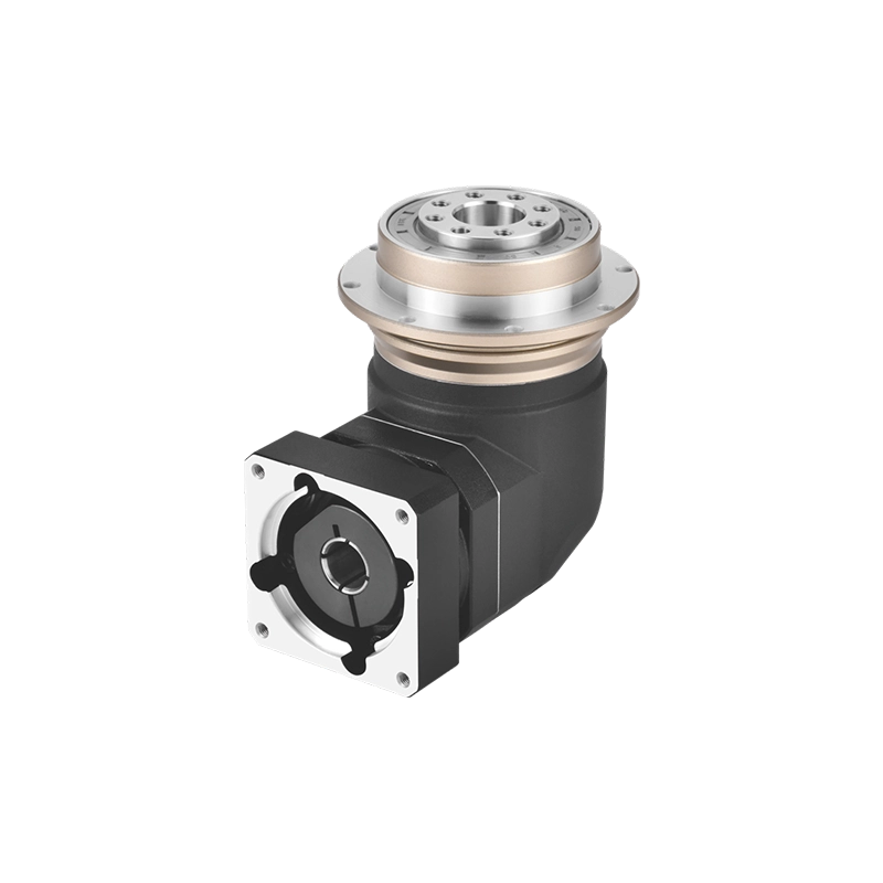
4. Planetary Gear Drive Indexing Table
A precision planetary reducer connects the servo motor to the table through simultaneous multi-point gear meshing. Low backlash (3–8 arcseconds for precision grades), high torsional stiffness, and coaxial geometry combine to make the planetary drive well-suited to servo-controlled indexing tables that also need to perform simultaneous-axis contouring.
The rotary index table mechanism based on a planetary drive doesn’t lock mechanically in the same way a Hirth coupling does — position is servo-held through the reducer. The advantage is flexibility: the table can index to any angle, not just fixed stations, and can interpolate continuously with other machine axes. For applications that need both indexing and contouring capability — or where station count changes between jobs — the planetary-driven table is the practical choice.
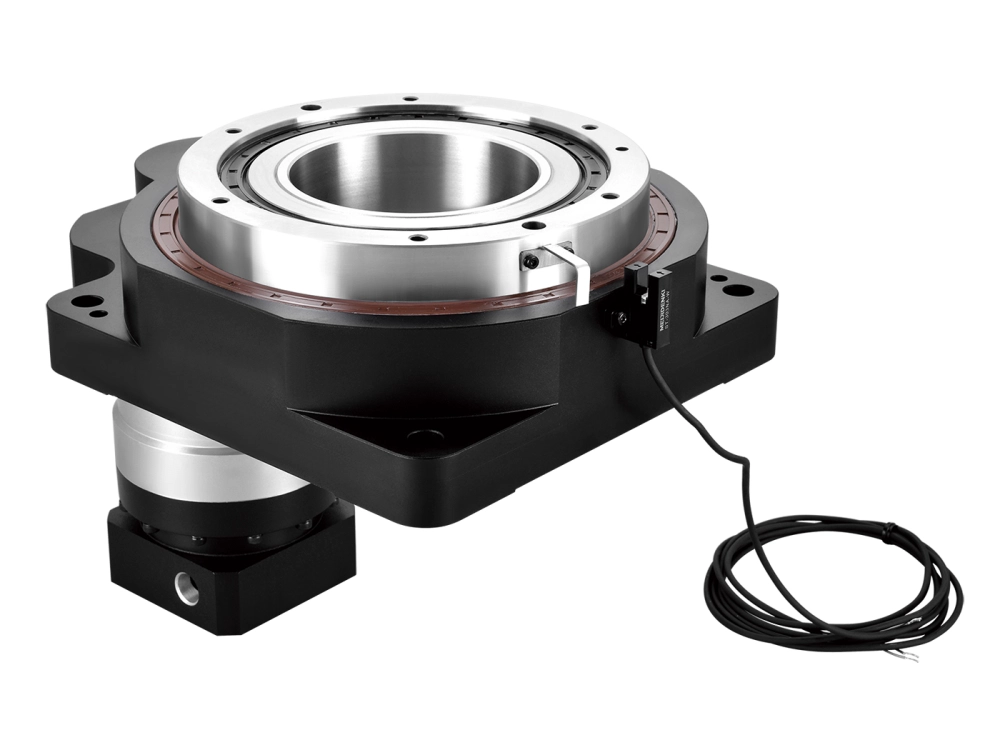
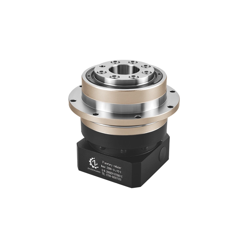
At Dongguan Zhuochuang Precision Machinery Co., Ltd, our indexing table drives are built on precision planetary reducers specifically for this reason: the hollow-centre configuration enables through-table utility routing, and the low-backlash performance supports both indexing and contouring use without changing the drive hardware.
Mechanical Rotary Indexing Table — Accuracy: Where the Numbers Come From
The positioning accuracy specification on a rotary indexing table datasheet needs to be understood in context. Two numbers matter:
Positioning accuracy — the worst-case deviation between the commanded angle and the actual angle, measured across all positions. A table rated at ±5 arcseconds means any commanded position will land within 5 arcseconds of its nominal value.
Repeatability — how consistently the table returns to the same position over many cycles. A table might have ±5 arcseconds absolute accuracy but ±1 arcsecond repeatability — meaning it consistently lands at the same spot, even if that spot is slightly offset from nominal. For production machining, repeatability often matters more than absolute accuracy, because the toolpath can be calibrated to the actual position.
What drives these numbers mechanically:
- Gear tooth geometry: Ground teeth hold tighter pitch and profile tolerances than hobbed teeth. The accumulated pitch error across the full ring gear circumference determines positioning error.
- Bearing preload and type: The table main bearing — typically a large-diameter crossed roller bearing or angular contact arrangement — determines the rigidity with which the table resists tipping and radial loads under cutting forces. Inadequate preload allows the table to deflect under load, corrupting the position.
- Thermal stability: As the mechanism heats up during operation, thermal expansion shifts gear mesh geometry. Designs that account for thermal behaviour (through housing material selection, cooling, or thermal compensation) maintain accuracy over a full production shift. Designs that don’t show accuracy drift between cold startup and warm operation.
- Coupling engagement (for Hirth designs): The accuracy of a Hirth-coupled table depends on the tooth form precision of the coupling, the axial clamping force (which determines tooth engagement depth), and the cleanliness of the mating surfaces.
Rotary Indexing Table Mechanism — Clamp and Brake Systems
The clamping system is as important as the drive mechanism, but gets less attention in most specifications.
Hydraulic clamping provides the highest clamp torque and the most rigid table lock. The hydraulic pressure acts on a piston that engages a clamp disc or collet-style mechanism integral with the table. Clamp torque can be specified to match the cutting forces of the application. Response time is fast — typically under 0.3 seconds for clamp and release — but requires a hydraulic supply.
Pneumatic clamping is simpler and lower cost, using shop air rather than a hydraulic power unit. Clamp torque is limited by available pneumatic pressure and piston area. For light to medium cutting loads, pneumatic clamping is adequate; for heavy milling or drilling, hydraulic is the correct choice.
Servo braking (holding position through the drive train) is not a substitute for mechanical clamping in production indexing applications. A servo can maintain a position setpoint, but it cannot match the rigidity of a mechanical clamp under interrupted cutting loads. For contouring applications where the table moves continuously, servo holding is appropriate because no mechanical clamp would be engaged anyway.
The clamp must be specified along with the drive: a high-precision planetary drive with an undersized pneumatic brake will show position shift under heavy milling loads. The system is only as good as its weakest element.
Selecting the Right Rotary Indexing Table Mechanism
Matching mechanism type to application requirements avoids both over-specification (paying for precision you don’t need) and under-specification (buying a system that drifts or fails early).
Station count fixed or variable? Fixed station count, high speed, maximum repeatability → cam-driven. Variable station count, flexible production → worm gear or planetary drive. Fixed station count, maximum accuracy, lower speed → Hirth coupling.
Cycle time requirements? Under 1 second per index for small tables → cam-driven. 1–5 seconds per index → any design; select on accuracy and cost. Over 5 seconds, complex motion profile → servo-driven planetary.
Machining load severity? Light to medium milling and drilling → pneumatic or worm self-lock. Heavy milling, large drill entries, interrupted cuts → hydraulic clamp.
Contouring required? Indexing only → any design. Simultaneous 4-axis interpolation → planetary drive with servo control.
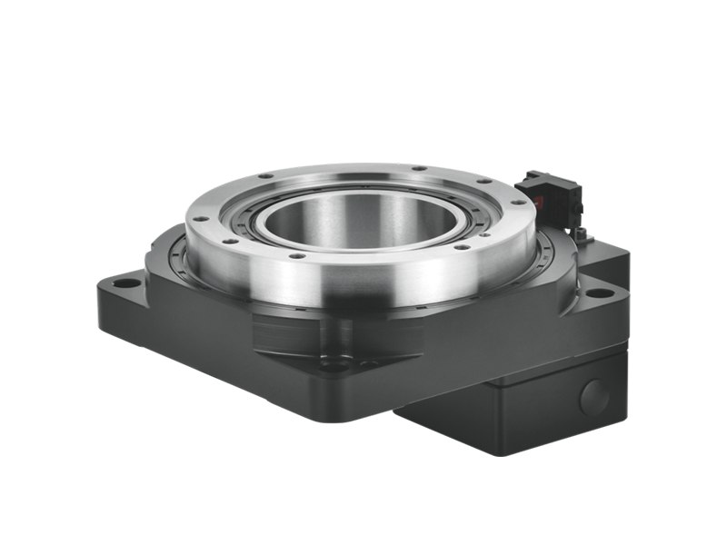
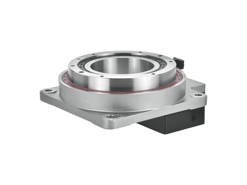
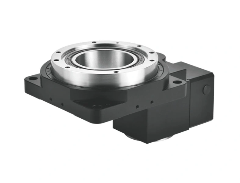
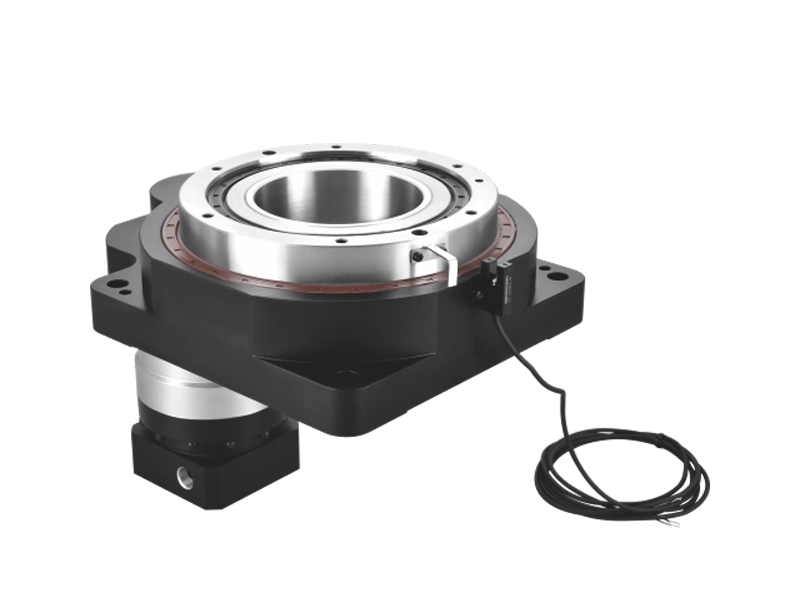
Through-bore required? Utility routing, automation, bar-stock access → hollow rotary indexing table with planetary drive.
What to Ask a Supplier
A rotary indexing table is a long-service-life component — properly specified and maintained, a quality unit runs for years in production without adjustment. Getting the specification right upfront matters.
Questions worth asking before ordering:
- What is the measured positioning repeatability on production units, and how is it measured?
- Is the gear tooth form ground or hobbed?
- What is the rated clamp torque, and how does it relate to the cutting force envelope of my application?
- What is the thermal drift specification — how much does positioning accuracy change between cold start and steady-state operating temperature?
- What through-bore diameter is available, and does it accommodate my utility routing requirements?
- Is the servo drive and motor included, or is integration the customer’s responsibility?
Suppliers who can answer these questions clearly are suppliers who understand the product. Those who respond with datasheet numbers only — without explaining how those numbers are achieved — are worth approaching with caution.
Summary
The rotary indexing table mechanism is not a commodity. The drive type — cam, worm gear, Hirth coupling, or planetary reducer — determines the cycle speed, positioning accuracy, flexibility, and long-term reliability the system delivers in production. Understanding these distinctions is what allows an engineer to specify a system that performs for years rather than one that meets the datasheet spec but falls short in practice.
At Zhuochuang, our indexing table solutions use precision planetary gear drives with hollow-centre configuration, designed for production environments where flexibility, accuracy, and automation compatibility all matter. If you’re working through a specification and want to talk through the mechanism options for your application, we’re ready to help.