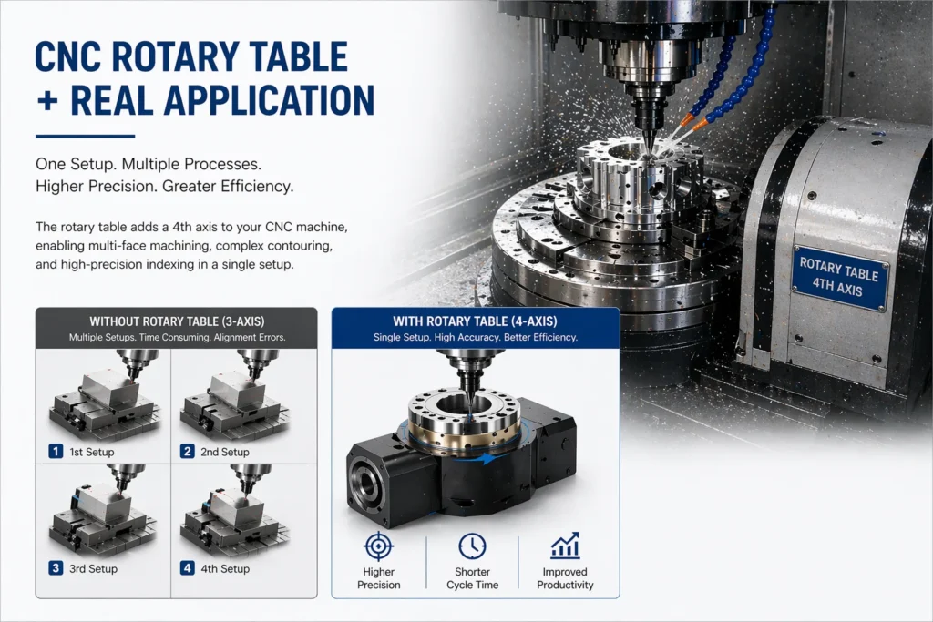
Three-axis CNC machining covers a lot of ground. X, Y, Z — you can mill flat faces, drill holes, cut pockets, and profile contours with no problem at all. What those three axes can’t do, without physically repositioning the workpiece, is machine a part from multiple angles in the same setup. Every time you break a setup to reposition, you introduce potential alignment error and add time to the cycle.
A rotary table solves that. It adds a controlled rotational axis — typically called the fourth axis — that rotates the workpiece while the spindle keeps cutting. The question most machinists and process engineers ask early on is a reasonable one: how does a rotary table work, exactly, and how does that translate into what the machine can actually produce?
That’s what this article covers. Mechanism, drive types, the role of the hollow rotary table in particular, and how the CNC rotary table fits into a machining operation from first principles.
How Does a Rotary Table Work — The Core Mechanism
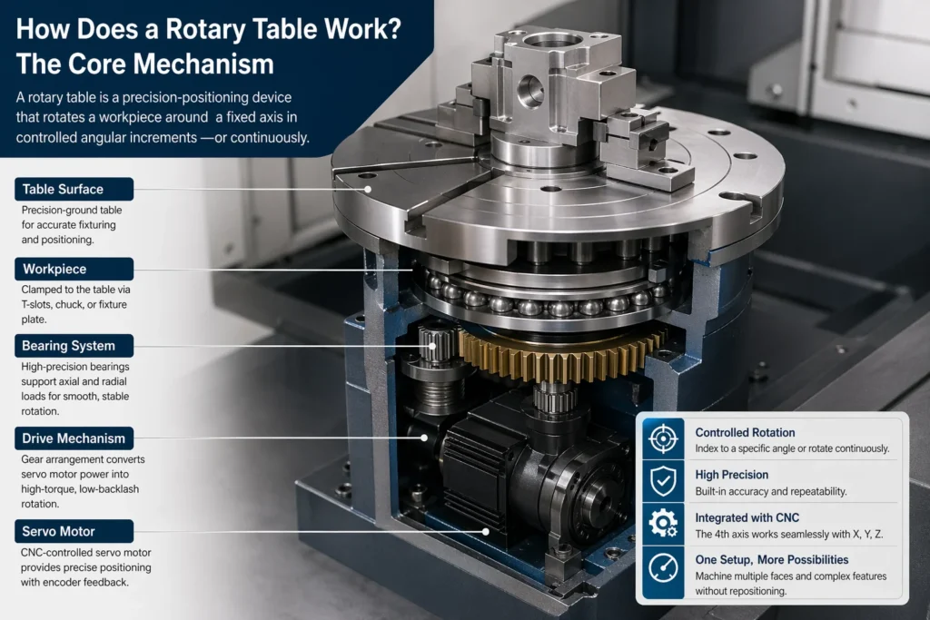
At its most basic, a rotary table is a precision-positioning device that rotates a workpiece around a fixed axis in controlled angular increments — or continuously, depending on the application.
The table surface is a hardened, precision-ground disc. The workpiece clamps to it via T-slots, a chuck, or a fixture plate. The disc is driven from below by a gear arrangement connected to either a servo motor (in CNC versions) or a handwheel (in manual versions). The drive mechanism determines how precisely the table positions and how stiffly it holds that position under cutting load.
How rotary table works in practice:
When integrated with a CNC machining centre, the rotary table’s rotational axis — usually designated the A-axis or B-axis depending on orientation — is controlled by the machine’s CNC controller alongside X, Y, and Z. The controller can command the table to index to a specific angle, hold it, and execute a machining operation; or it can drive continuous simultaneous rotation while the linear axes move, producing helical cuts, curved profiles, or complex 3D contours.
The result is a machine that can address multiple faces of a part, drill bolt circles at precise angular intervals, mill gear teeth, or cut cam profiles — all without unclamping the workpiece.
Rotary Table Mechanism — What’s Inside and Why It Matters
The performance of any CNC rotary table comes down to one thing: the drive mechanism. This is where precision is either built in or isn’t — and no amount of software compensation fully recovers what a poor mechanical foundation loses.
Worm and worm gear is the traditional arrangement. A worm shaft meshes with a large-diameter worm gear attached to the table. The geometry creates a high reduction ratio in a compact radial space, and the worm arrangement is inherently self-locking — the table won’t back-drive under cutting load. Backlash is the main limitation. Standard worm drive tables typically have backlash in the range of 10–30 arcseconds. Precision models with preloaded dual-lead worm gears bring this down to 5 arcseconds or less.
Direct drive (torque motor) eliminates the intermediate gear entirely. The motor rotor is directly coupled to the table, with a high-resolution encoder reading position. Zero mechanical backlash, very high torsional stiffness, fast response. The tradeoff is cost and the requirement for a high-quality encoder and servo drive. Direct drive tables are standard in five-axis machining centres and high-speed contouring applications where the rotary axis must keep up with rapid, continuous path changes.
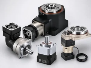
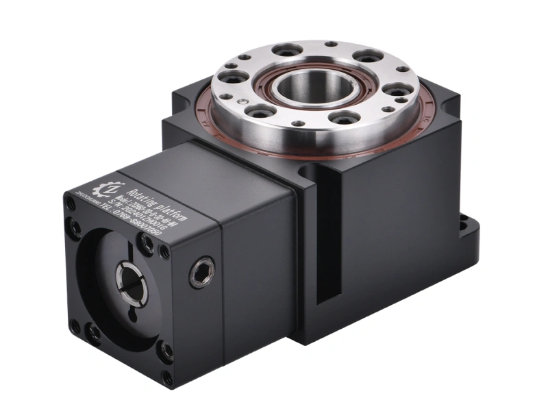
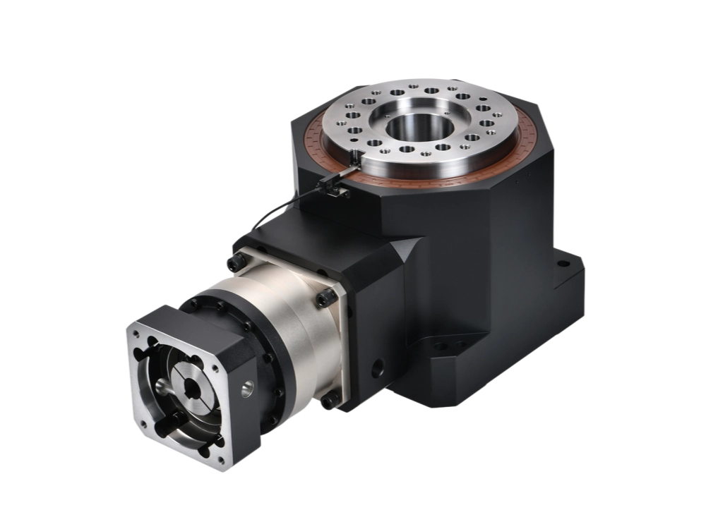
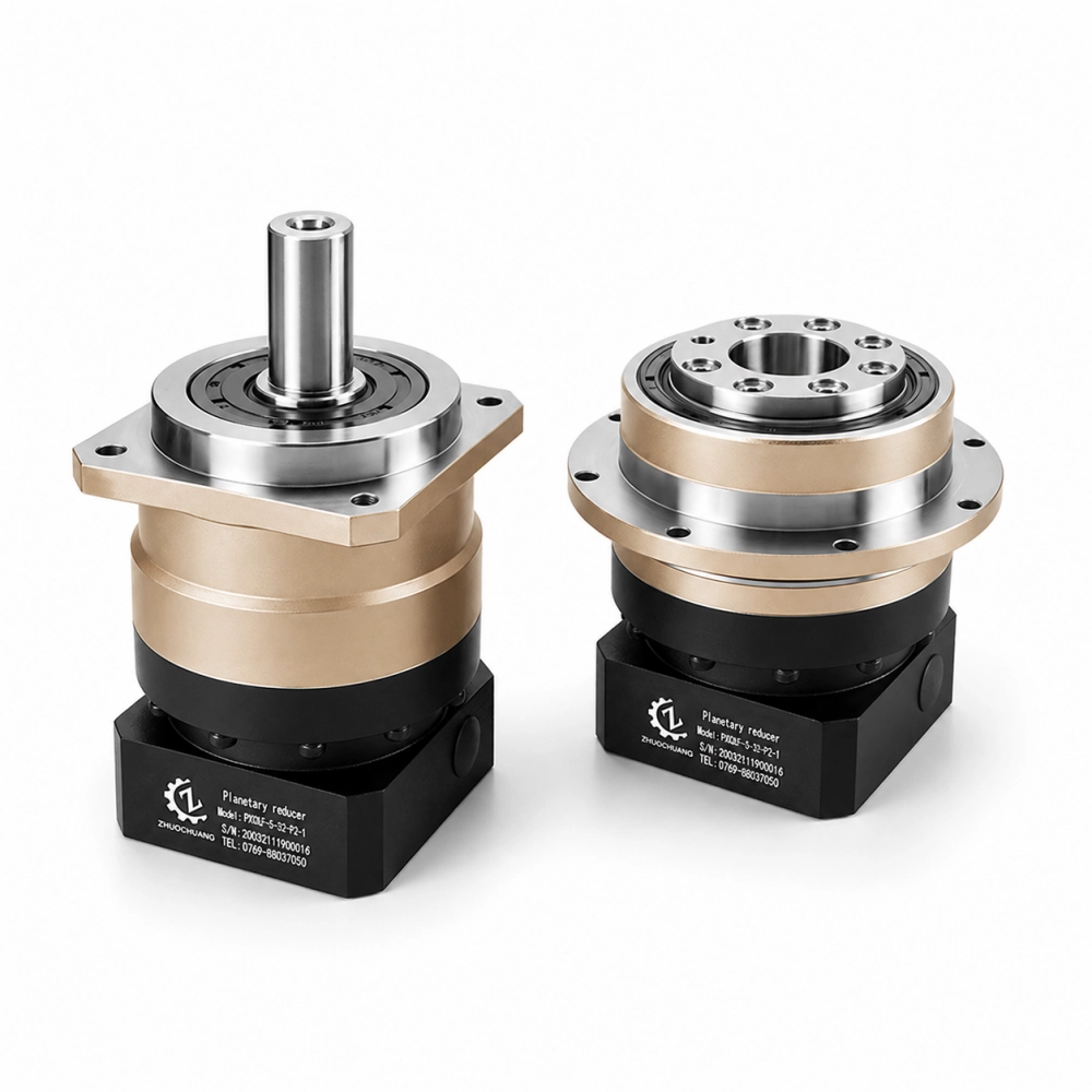
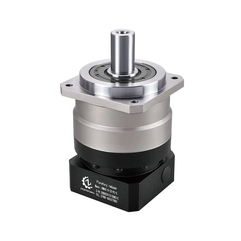
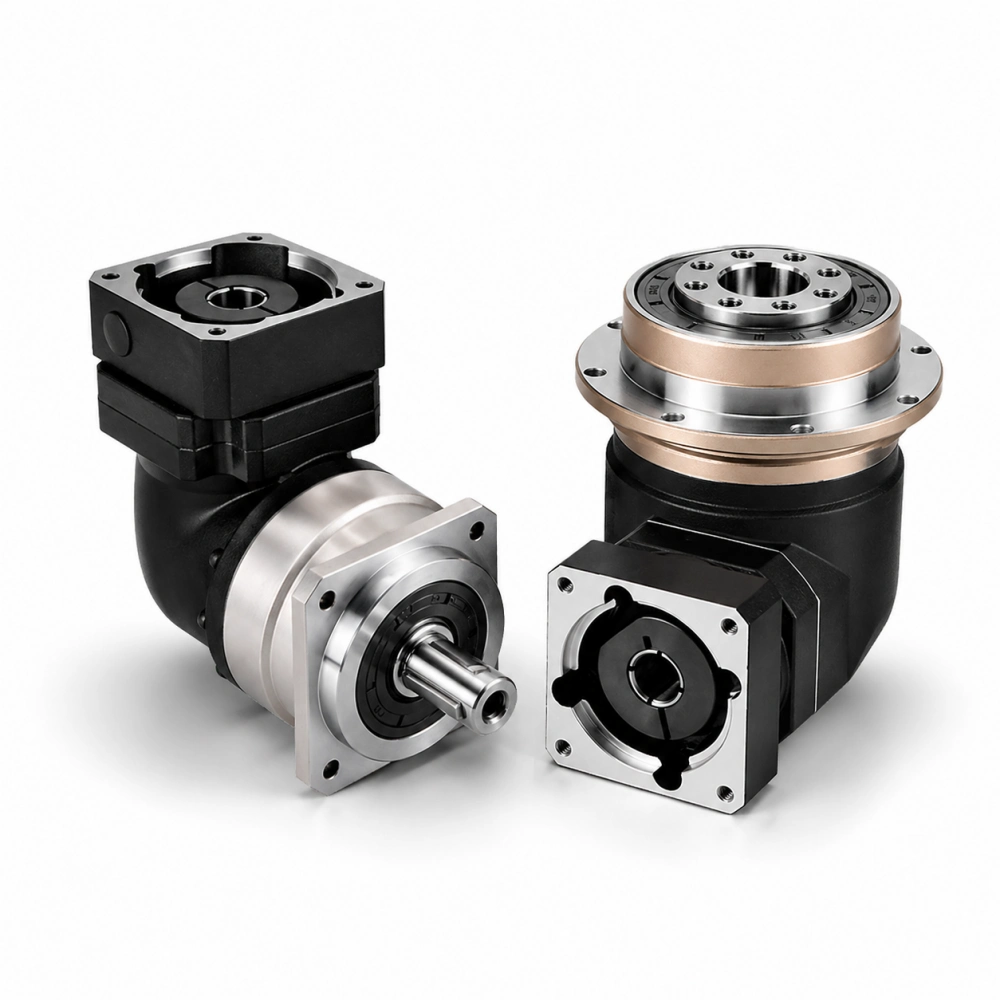
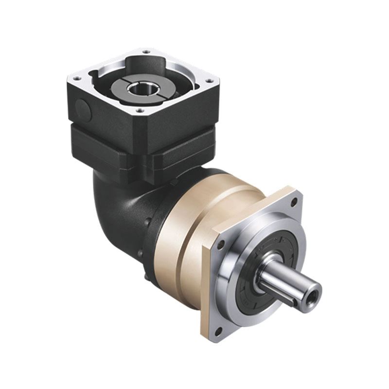
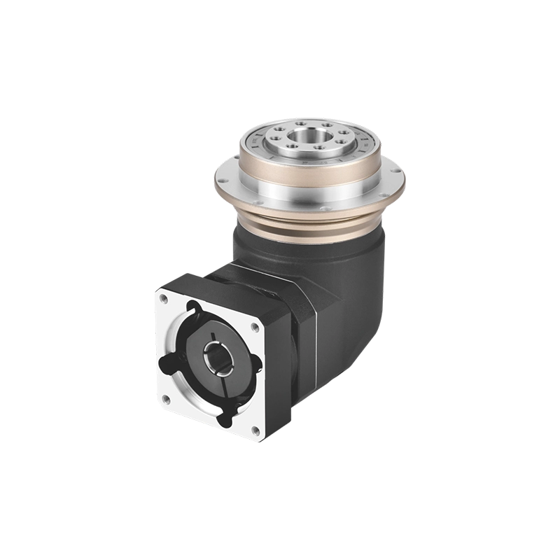
Planetary gear drive — the arrangement Zhuochuang builds — sits between worm and direct drive in terms of cost and performance. A precision planetary reducer connects the servo motor to the table through multiple simultaneous gear meshes, producing high torque output with low backlash. The coaxial design keeps the rotary table compact and enables the hollow-centre configuration that’s critical for many CNC applications. More on that below.
The rotary table mechanism you choose should match your application’s actual requirements. For general indexing work, a quality worm drive is sufficient. For simultaneous 4-axis contouring or applications with frequent direction reversals, planetary or direct drive gives noticeably better results.
CNC Rotary Table — How It Integrates With Your Machine
A CNC rotary table is fundamentally different from a manual one not in how it positions, but in who — or what — controls that positioning. In a manual table, the machinist turns a handwheel and reads a graduated dial. In a CNC table, the servo motor receives position commands from the machine controller, executes them with encoder feedback, and holds the position under load without human input.
The integration path is straightforward on modern machining centres: the rotary table’s servo drive connects to the machine’s axis control system, the table is characterised in the machine parameters (gear ratio, encoder resolution, axis limits), and the CNC program addresses the rotary axis the same way it addresses X, Y, or Z. From that point, you can write programs that index the table between operations or drive it simultaneously with linear axes.
What changes operationally:
Multi-face machining in a single setup. A prismatic part with features on four sides can be fixtured once, rotated 90° between operations, and fully machined without ever breaking the clamp. Setup error from repositioning disappears. Cycle time drops.
Bolt circles and angular patterns. Drilling 12 holes evenly spaced on a 150mm PCD — the rotary table indexes to each 30° position while the spindle drills. No layout, no error accumulation.
Continuous contouring. With the rotary axis interpolated against linear axes, the machine can cut involute gear profiles, helical grooves, cam contours, and complex 3D surfaces that would otherwise require a five-axis machine or multiple specialised setups.
Reduced fixturing complexity. Because the workpiece can be rotated to present any face to the spindle, many parts that previously needed custom angle plates or compound fixtures can be held in straightforward vices or chucks on the rotary table.
Hollow Rotary Table — Why the Through-Hole Changes Everything
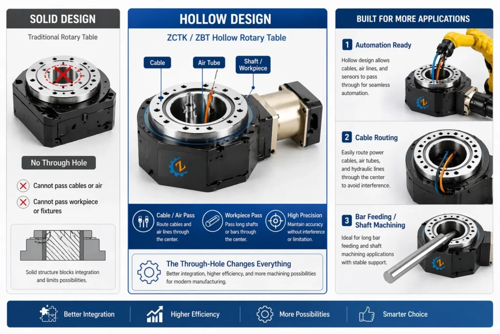
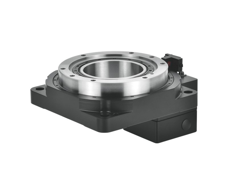
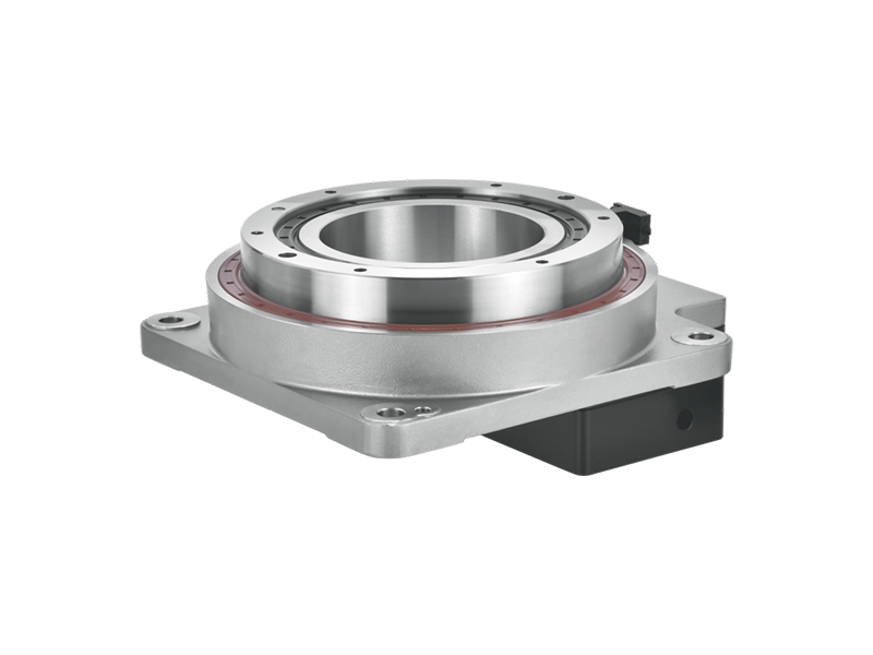
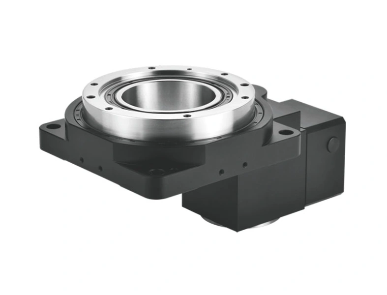
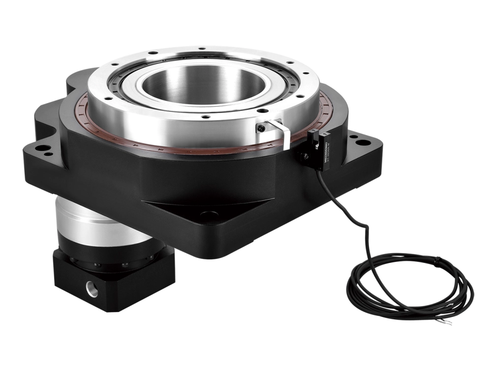
The hollow rotary table is a specific configuration worth understanding separately, because it unlocks capabilities that a solid-centre table simply cannot provide.
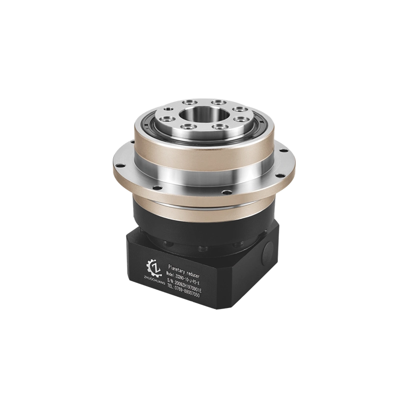
A hollow rotary table has a large-diameter through-hole running through the centre of the table and the drive mechanism. Depending on the model, this bore might be 50mm, 100mm, 200mm, or larger. That bore serves several functions:
Workholding through the centre. Bar stock, tubing, or shaft-type components can pass through the table bore from the back, clamped at the front face. This enables turning-style operations on a machining centre — rotating bar stock for milling, drilling, or profiling along its length — without a separate lathe operation.
Routing of utilities. In automated cells, coolant lines, pneumatic clamp supply, hydraulic actuators, and electrical signals for powered fixtures all need to reach the rotating table surface. The through-hole provides the path. Without it, these connections either wrap around the outside (creating rotation limits and cable management problems) or pass through a rotary union mounted separately.
Laser and inspection tool access. Some applications require a laser beam, measurement probe, or camera to access the underside of a rotating part. The hollow centre provides that access without interrupting the fixturing arrangement.
Integration with automation. In production environments with robot loading, a hollow rotary table can accommodate a through-spindle gripper or collet mechanism, enabling automated part loading and unloading through the table centre. This is increasingly common in cell-based machining for high-volume precision parts.
The hollow configuration is mechanically more demanding than a solid-centre design. Maintaining rigidity and low backlash when the centre of the load path is absent requires careful attention to bearing arrangement and drive geometry. This is an area where planetary gear drive designs have an inherent advantage: the coaxial, distributed-load nature of the planetary reducer works naturally with a hollow centre shaft, keeping the overall assembly compact and stiff.
Indexing vs. Contouring — Choosing the Right Mode
CNC rotary tables operate in two fundamentally different modes, and understanding the distinction is important when specifying the table and writing the machining program.
Indexing mode: The table rotates to a commanded angle, a clamp or brake engages to lock the table rigidly, and the machining operation runs. The rotary axis is stationary during cutting. This is the correct approach for drilling, milling faces, tapping, and any operation where the cutting forces are large and the table needs to be mechanically locked rather than servo-held. Indexing mode is less demanding on the drive mechanism and works well with worm gear designs.
Contouring mode (simultaneous 4-axis): The rotary axis moves continuously, interpolated with the linear axes, while cutting is in progress. The servo drive must hold position against cutting loads dynamically, without the assistance of a mechanical brake. This demands a stiffer, lower-backlash drive arrangement. If the table has residual backlash or low torsional stiffness, the contoured path will show errors — visible in the surface finish of the part.
Most applications on general machining centres are indexing mode. Contouring becomes necessary when the part geometry genuinely requires it: helical features, cam profiles, complex turbine or impeller geometry, and similar contoured surfaces. If your application is primarily indexing, don’t over-specify the table for contouring performance — and vice versa.
What to Specify — A Practical Checklist
When selecting a CNC rotary table for a machining application, the following parameters drive the decision:
Table diameter and load capacity. The table must accommodate your largest workpiece and fixture combined, within the machine’s work envelope. Load capacity (face load and eccentric load) must cover the actual weight and centroid offset of your fixturing arrangement, not just the part weight.
Through-bore diameter. If you need hollow rotary table capability — for utility routing, bar stock access, or automation — specify the required bore size upfront. The bore size drives the entire mechanical design of the unit.
Backlash. For indexing operations, 10–15 arcseconds is usually adequate. For simultaneous contouring, specify 5 arcseconds or less. For high-precision contouring, consider direct drive.
Positioning accuracy and repeatability. Accuracy is the absolute position error at any commanded angle. Repeatability is how consistently the table returns to the same position. For most industrial applications, repeatability matters more than absolute accuracy.
Interface to your machine controller. Confirm motor and drive compatibility with your machine’s control system before ordering. Not all servo drives speak the same protocol.
Brake or clamping system. For heavy-duty indexing, a hydraulic or pneumatic clamp provides the rigidity that a servo brake alone cannot. Specify clamp torque adequate for your cutting forces.
Closing
Understanding how does a rotary table work is the foundation for using one correctly. The mechanism — drive type, bearing arrangement, hollow or solid centre, indexing or contouring capability — determines what the table can deliver and under what conditions it delivers it reliably.
At Dongguan Zhuochuang Precision Machinery Co., Ltd, our hollow rotary tables and CNC rotary table units are built around precision planetary gear drives designed for the conditions that matter in production machining: consistent positioning, adequate stiffness for real cutting loads, and the hollow-centre configuration that automation and utility routing require. If you’re specifying a rotary axis for a new cell or retrofitting an existing machine, we’re glad to work through the application requirements with you.