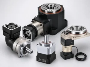
If you’ve ever watched a robotic arm move with uncanny precision, or wondered what keeps a CNC spindle turning smoothly under load, the answer often traces back to a single mechanical component: the planetary gearbox. Engineers reach for it constantly — in automation, in heavy machinery, in precision motion control — because nothing else delivers the same combination of torque density, compact form, and mechanical efficiency in one package.
So: how does a planetary gearbox work? That’s what this guide covers, from the basic gear arrangement right through to why precision matters in the real world. Whether you’re specifying a drive system for the first time or revisiting fundamentals, the mechanics are worth understanding properly.
How Does a Planetary Gearbox Work — The Core Mechanism
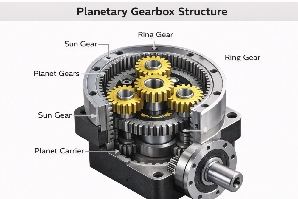
At its heart, a planetary gearbox uses three types of gears working in concert: a sun gear at the center, a set of planet gears that orbit around it, and a ring gear (also called an annulus) that wraps around the outside with internal teeth.
Here’s how the motion flows in the most common configuration:
- The sun gear is driven by the motor — it’s your input. It’s small, it spins fast.
- The planet gears mesh with the sun gear and roll around it. They’re held in position by a planet carrier.
- The ring gear is fixed to the housing — it doesn’t rotate. The planets roll against its inner teeth as they orbit.
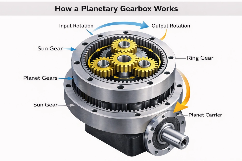
- As the planets orbit, the carrier rotates — and that carrier is your output shaft.
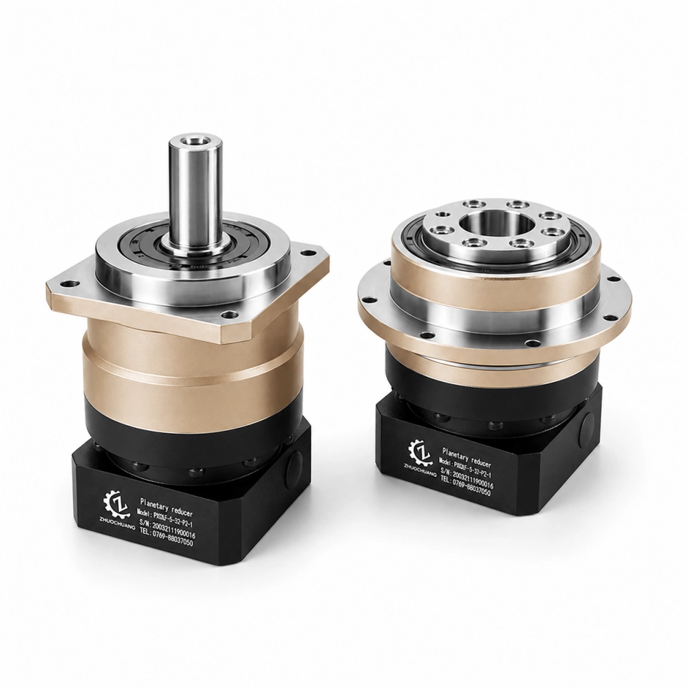
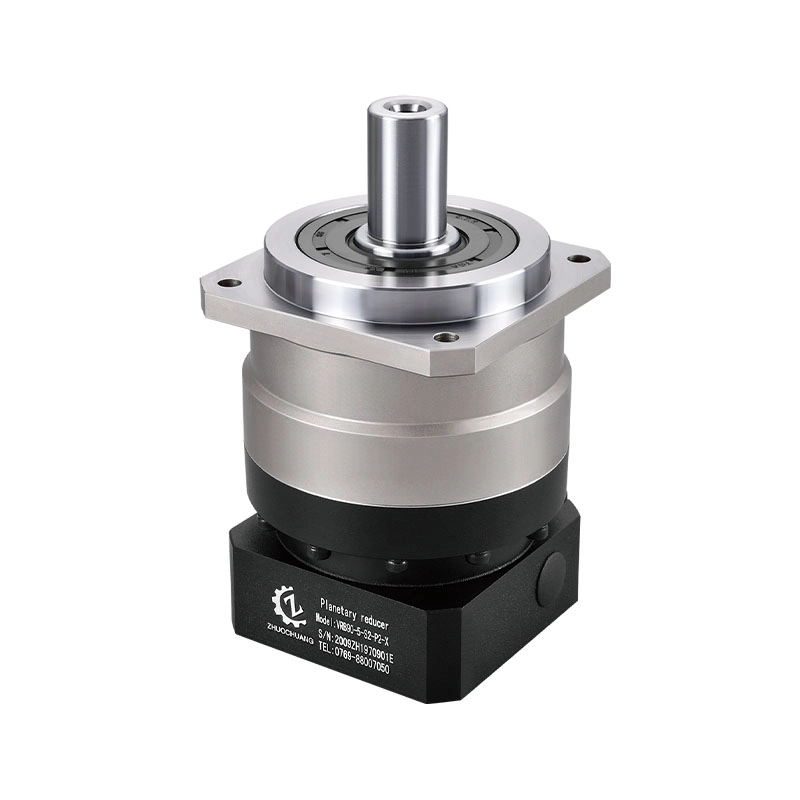
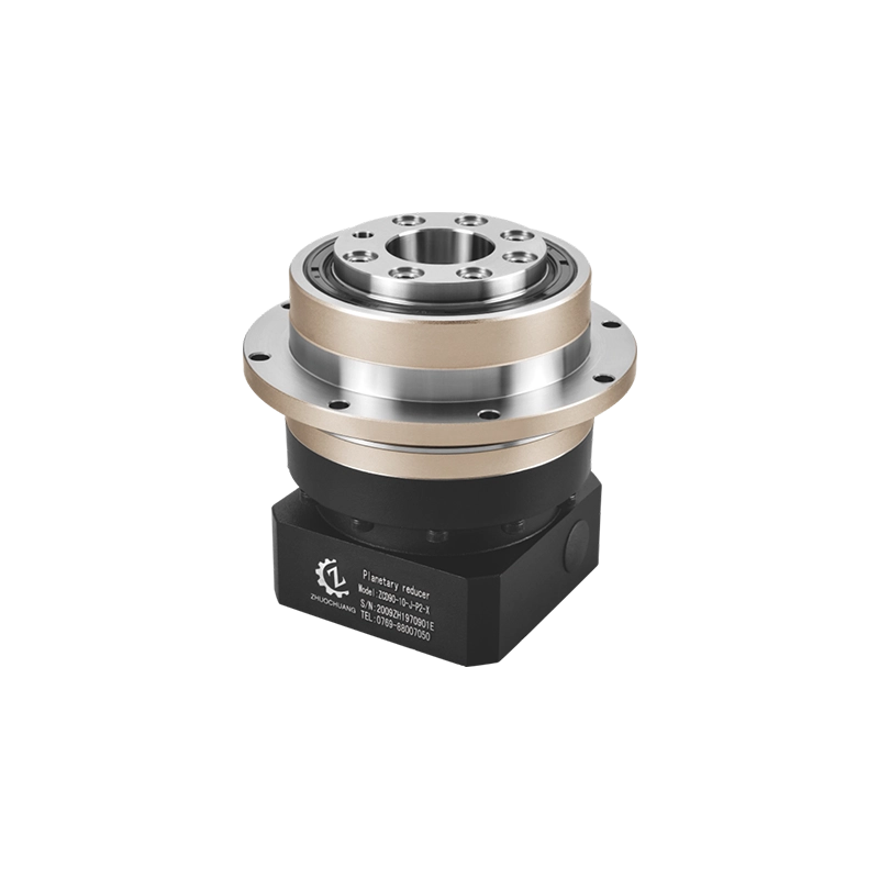
The result: a high-speed motor input becomes a lower-speed, higher-torque output, all within a compact cylindrical housing where input and output share the same axis.
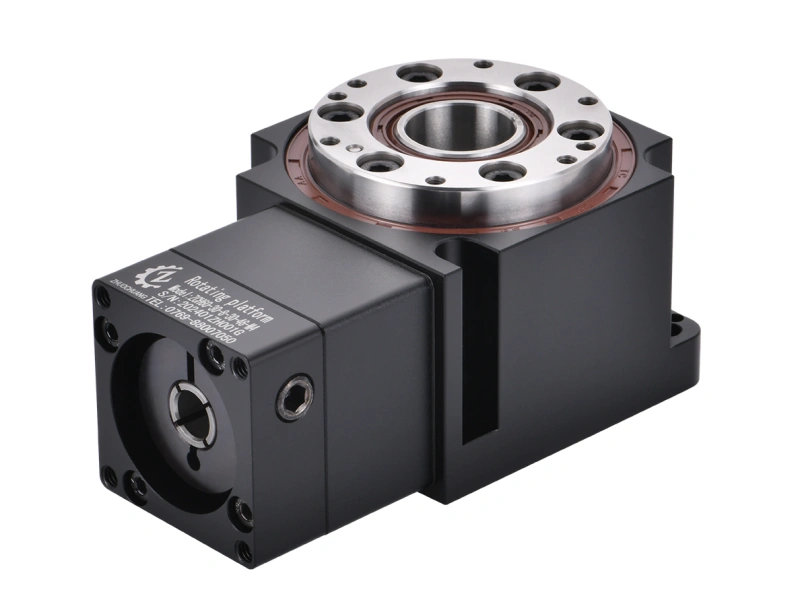
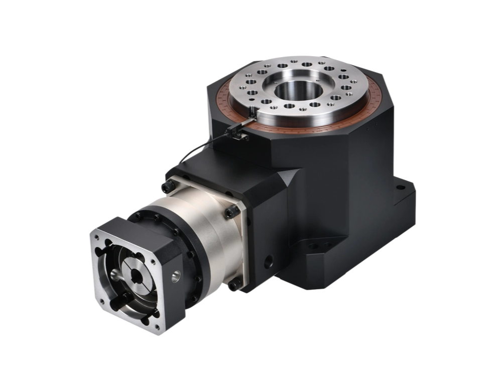
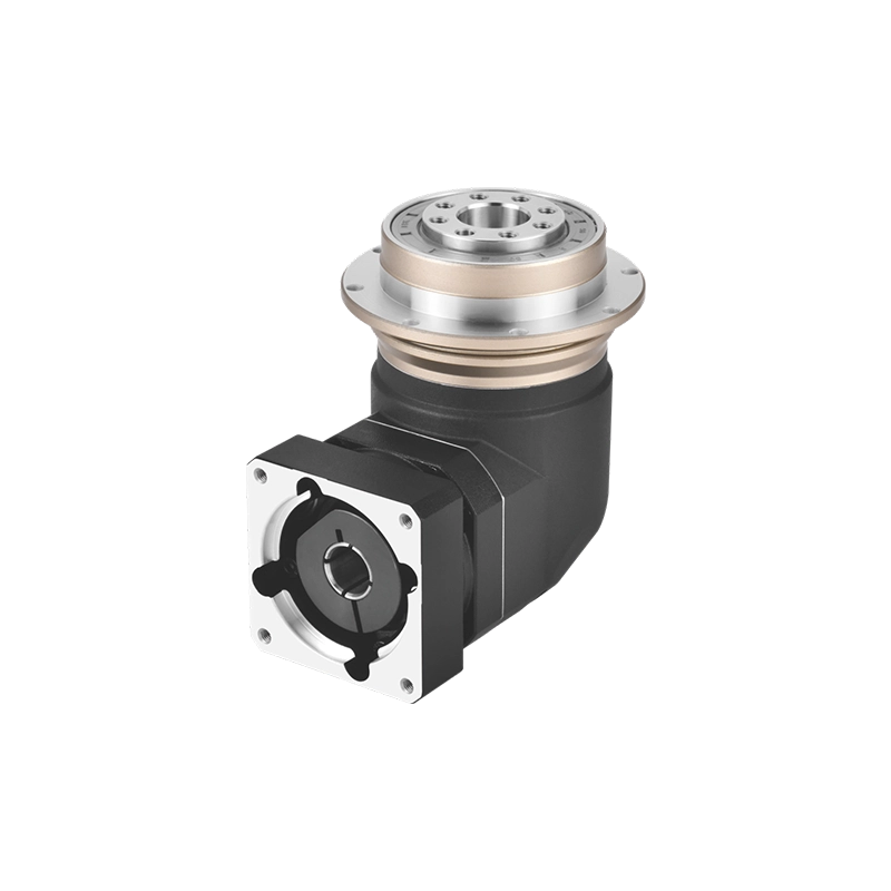
This is what makes the planetary gearbox fundamentally different from a parallel-shaft helical gearbox: the coaxial design. Input shaft and output shaft are inline, which simplifies mounting, saves space, and enables clean integration into tight mechanical assemblies.
What Is a Planetary Gearbox — And What Makes It Different
Understanding what is a planetary gearbox means understanding the problem it was designed to solve.
Electric motors are efficient at high speeds and relatively low torque. Most industrial applications need the opposite: significant torque at controlled, often slow speeds. A gearbox bridges that gap by trading speed for torque — and the gear ratio determines exactly how much of each you get.
What separates a planetary gearbox from simpler alternatives is how it handles that conversion. In a standard gearbox, one gear meshes with one other. All the torque passes through a single contact point. Under load, that single point bears the full mechanical stress — which limits how much torque the unit can handle without increasing its physical size.
In a planetary arrangement, the load is split across multiple planet gears simultaneously. With three planet gears, each contact point carries roughly one-third of the total torque. This is why planetary gearboxes deliver higher torque from a smaller package than equivalent parallel-shaft designs. It’s not a minor advantage — it’s often the deciding factor when space and load requirements are both demanding.
Planetary Gearbox Explained — The Load Distribution Advantage
When engineers say a planetary gearbox is “efficient,” they usually mean two things at once: power transmission efficiency and mechanical load efficiency. Both come from the same source — the way load is shared across the gear mesh.
Power transmission efficiency in a well-built planetary stage typically sits between 97% and 99% per stage. Most of what goes in comes out as useful work, with minimal heat loss. Stack two stages and you’re still at 94–98% overall — better than many belt or chain alternatives.
Load distribution means that radial forces from the planet gears cancel each other out around the sun gear. Because the planet gears are evenly spaced, the radial loads they exert on the sun gear bearing are balanced. This dramatically reduces bearing stress and extends service life compared to designs where radial loads accumulate on a single mesh.
The combined result: a planetary gearbox explained properly isn’t just “it uses planetary gears.” It’s a system where the geometry itself is doing structural work — distributing stress, balancing forces, and maximizing the ratio of output torque to unit weight.
This is why gearbox planetary gear arrangements dominate applications where the mechanical environment is genuinely demanding: high cycle counts, continuous duty, variable loads, and long service intervals without maintenance access.
Planetary Gearbox How It Works — Gear Ratios and Stage Design
One of the most practical questions about planetary gearbox how it works is also the most concrete: how do you get the ratio you need?
For a single planetary stage with the ring gear fixed:
Ratio = (Ring gear teeth ÷ Sun gear teeth) + 1
Example: a ring gear with 72 teeth and a sun gear with 24 teeth gives (72 ÷ 24) + 1 = 4:1. Every four rotations of the motor produces one rotation of the output shaft, at four times the torque (minus losses).
Single stages typically achieve ratios between 3:1 and 10:1. For higher reductions — 20:1, 50:1, 100:1, or beyond — multiple stages are placed in series. The output carrier of stage one becomes the input sun gear of stage two. Two-stage units cover most industrial servo and motion control applications. Three-stage units handle the high-ratio, high-torque end of the spectrum.
What makes this flexible is that the ratio can be changed by adjusting only the sun and ring gear tooth counts, without fundamentally redesigning the housing or planet carrier. This modularity is part of why planetary gearboxes are so widely used across industries with very different drive requirements.
How a Planetary Gearbox Works in Precision Applications — Backlash and Accuracy
Understanding how a planetary gearbox works at the mechanical level is one thing. Understanding how it performs in a precision application is where the real engineering begins.
The key metric is backlash — the rotational play between input and output when direction reverses. In a conveyor drive, a few arcminutes of backlash is irrelevant. In a CNC machine axis or a collaborative robot joint executing a programmed path, backlash introduces positioning error that accumulates with every direction change.
Standard planetary gearboxes typically have backlash in the range of 15–25 arcminutes. Acceptable for many general industrial uses, but not for motion control.
Precision planetary gearboxes — the type used in servo-driven systems — are designed and manufactured to a different standard:
- Ground gear teeth rather than hobbed or shaved, for tighter tooth geometry tolerances
- Controlled bearing preload to eliminate axial and radial play in the carrier assembly
- Optimized planet carrier geometry to maintain consistent mesh across operating conditions
- Backlash figures below 3 arcminutes for high-precision grades, sometimes below 1 arcminute for the most demanding applications
The difference between a 15-arcminute and a 3-arcminute unit isn’t just a spec on paper. In a robot arm with a 500mm reach, 12 arcminutes of additional backlash translates to roughly 1.7mm of positioning error at the tool — which is the difference between a usable joint and one that can’t hold tolerance.
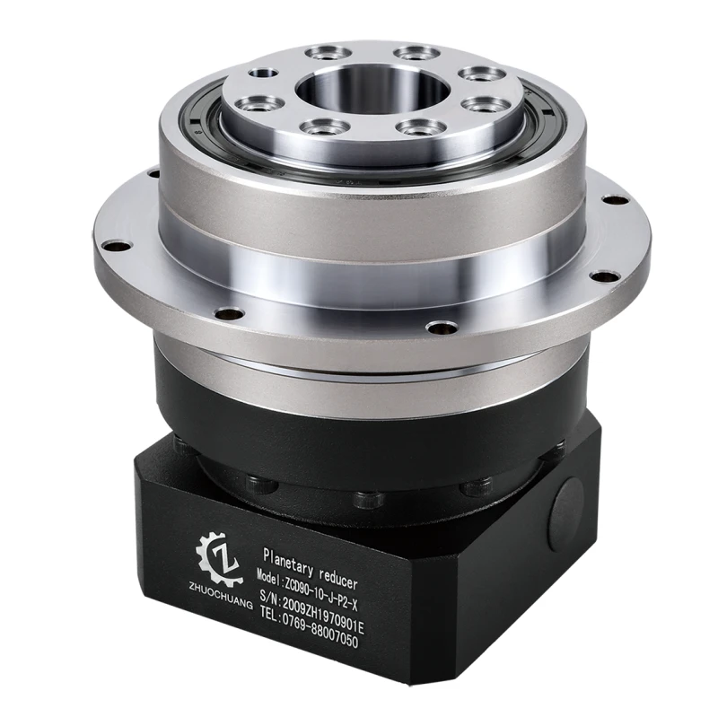
At Zhuochuang, precision planetary gearboxes are what we build. Our units go into applications where that positioning error matters: automated assembly, laser cutting heads, semiconductor handling, and multi-axis robotic systems where every joint in the kinematic chain has to perform.
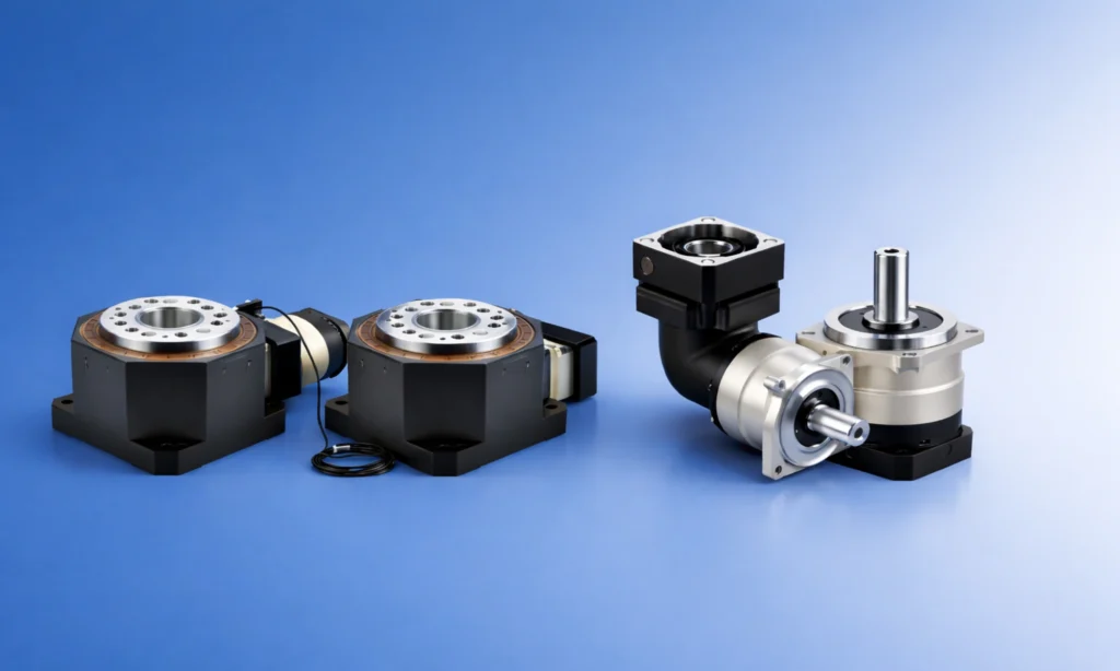
Planetary Drive Gearbox — Real-World Applications
The range of equipment that depends on a planetary drive gearbox reflects how broadly useful the design is. A short list:
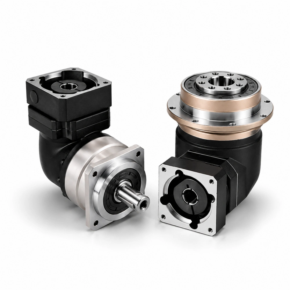
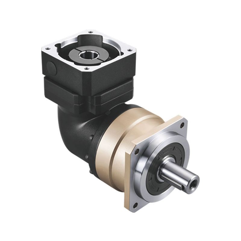
Industrial robots and cobots — every rotary joint in a multi-axis robot arm is typically a planetary stage. The torque density and backlash performance are both critical.
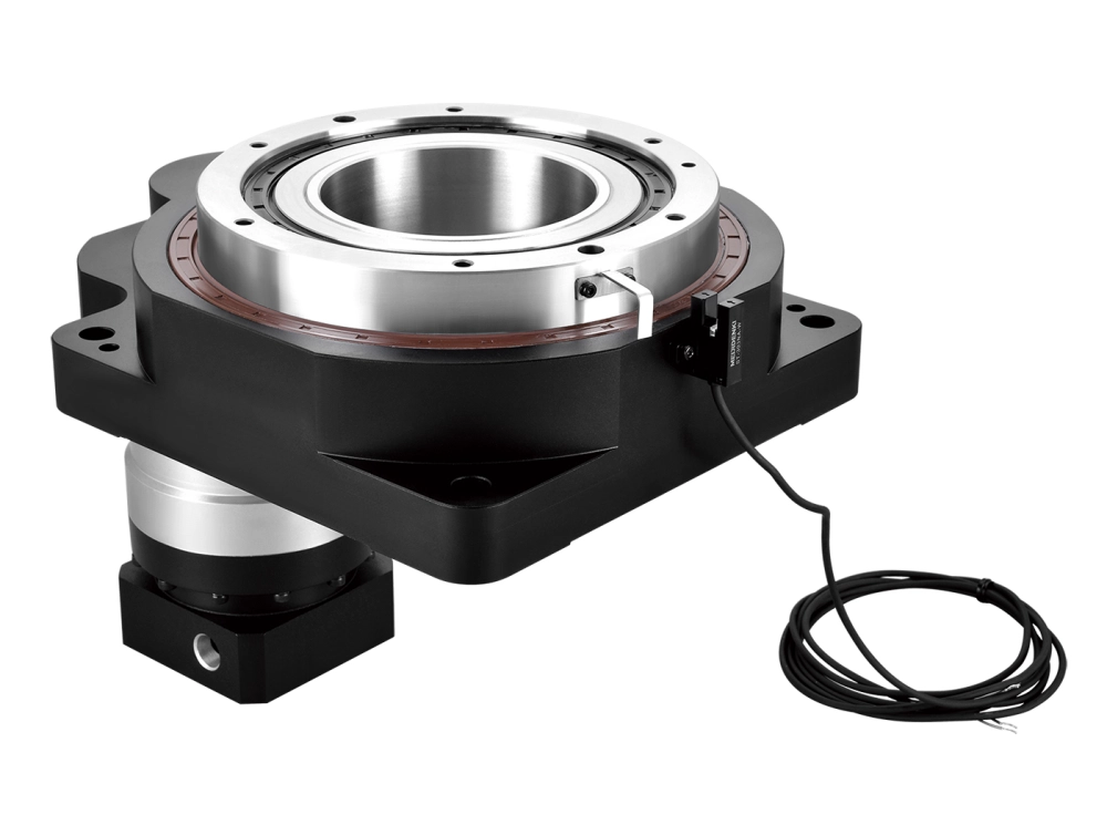
CNC machine tools — rotary tables, spindle heads, and tool-change mechanisms use planetary gearboxes for the stiffness and positioning accuracy they require under cutting loads.
Automated guided vehicles (AGVs) — wheel drive and steering systems need compact, sealed, high-cycle-capable reducers. Planetary units handle the combination of load and duty cycle better than alternatives.
Packaging and food processing machinery — rapid indexing, high cycle rates, and the need for backlash control in positioning applications make planetary gearboxes standard in this sector.
Semiconductor and electronics manufacturing — wafer handling and precision positioning stages use the lowest-backlash planetary grades available, often with additional preload to eliminate all detectable play.
Wind energy — large-scale planetary arrangements in wind turbine nacelles handle the enormous torque from rotor blades, stepping up rotational speed for the generator. This is planetary gear technology at its maximum scale.
Selecting the Right Planetary Gearbox — What Actually Matters
Knowing how a planetary gearbox works is the foundation. Selecting the right one for your application requires translating that understanding into specifications.
Gear ratio: Start with your required output speed and input speed. The ratio follows directly. Consider whether a single stage gets you there, or whether you need two.
Output torque and peak torque: Rated torque is the continuous operating value. Peak torque (typically 2–3× rated) must accommodate acceleration loads and shock events without tooth damage.
Backlash: Define the maximum positioning error your system can tolerate. Work backward from the application accuracy requirement through the kinematic chain to a backlash budget for the gearbox.
Mounting interface: Output flange, shaft diameter, input adapter for your motor — these need to match your mechanical design before anything else matters.
Duty cycle and service life: High-cycle applications wear gear teeth and bearings faster. Specify the expected operating hours and cycle rate so the unit is sized for service life, not just peak torque.
Supplier capability: A gearbox is only as good as the tolerances it was built to. Ask for backlash measurement data, tooth contact pattern documentation, and the manufacturing processes used. A supplier who can answer those questions is a supplier who understands what they’re building.
Summary
How does a planetary gearbox work? Three gear types — sun, planet, and ring — arranged so that load is shared across multiple simultaneous mesh points, producing high torque output from a compact coaxial package. The gear ratio comes from the relationship between sun and ring gear tooth counts, with multiple stages available for higher reductions.
What separates a good planetary gearbox from a great one is the precision of its manufacture: tooth geometry, bearing preload, carrier accuracy, and the backlash figure that results from all of them together.
If you’re specifying a drive system and want to work through the numbers — ratio, torque, backlash, mounting — we’re glad to help.