
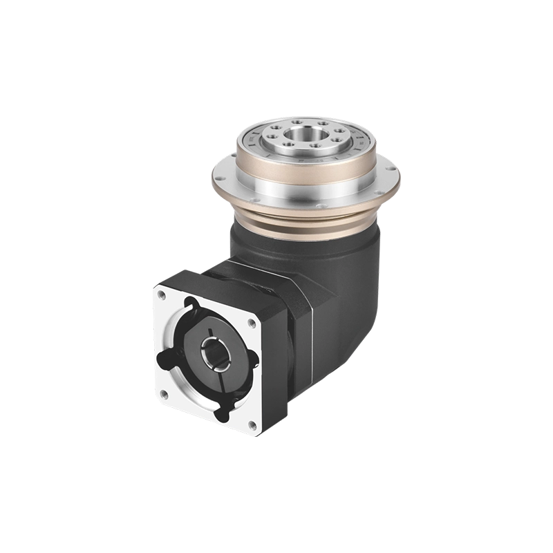
Field procedure for servo-driven machinery
A planetary gearbox can have the correct ratio, torque rating and motor adapter yet still fail during commissioning. The cause may be a contaminated locating face, an incorrect sleeve, a coupling that bottoms on the motor shaft, uneven flange tightening or a motor pulled into alignment by its bolts.
This planetary gearbox installation guide follows the job from the unopened components to the first loaded run. It is written for compact precision reducers connected to servo or stepper motors—not large oil-filled industrial drives. Always place the selected gearbox drawing, motor drawing and model-specific instructions beside this guide. Where they differ, the manufacturer’s instructions control.
Preparing a Planetary Gearbox Installation?
Send the motor model, gearbox model, ratio, mounting orientation and machine drawing. We can check which shaft, pilot, flange and adapter dimensions must be confirmed before assembly.
Check Motor and Gearbox Compatibility →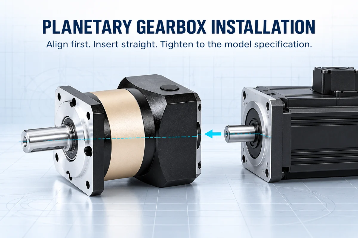
Planetary Gearbox Installation Starts Before Assembly
Keep the motor and reducer protected until the work area is ready. Installation should be performed by personnel who understand rotating machinery, safe lifting, torque tools and the machine’s lockout procedure. Isolate power and prevent unintended shaft movement before touching the drive.
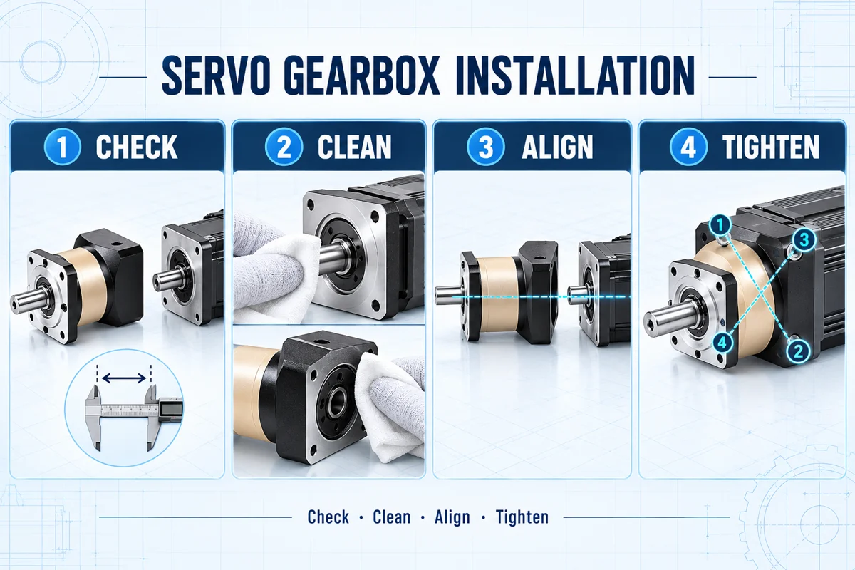
Confirm the delivered model, ratio, precision grade, output style and adapter code against the purchase order. Check for shipping damage, a bent shaft, damaged threads, missing plugs or contamination around seals. Do not begin planetary gearbox mounting if the shaft does not rotate as expected or the housing shows impact damage.
Steps 1–2: Confirm the Servo Motor and Planetary Gearbox Mounting Interface
Motor power and frame name are not enough. Two motors with similar ratings may have different shafts, pilots or bolt patterns. The pilot centers the motor relative to the gearbox input; the bolts retain the flange. Using bolts to compensate for an incorrect pilot fit can introduce misalignment even if all four bolts enter their holes.
Check that the motor shaft will not bottom inside the input bore and that the clamping area will contact the intended portion of the shaft. If a sleeve is specified, confirm its orientation and that it sits fully in the input clamp. Never stack improvised sleeves or modify a motor shaft during servo gearbox installation without an approved drawing.
Steps 3–4: Clean the Shaft for Planetary Gearbox Mounting
Use a lint-free cloth and a cleaning method compatible with the seals and coatings. Do not allow solvent or debris to enter the gearbox. A particle trapped between the flanges can tilt the motor; a burr on the pilot can prevent full seating; oil on a friction-clamped shaft can reduce holding capacity. Conversely, do not remove a lubricant or assembly compound that the product instructions specifically require.
Inspect the shaft for raised edges around a keyway or flat. Check visible runout or damage before assembly. In practical precision-drive assembly, cleanliness, geometric compatibility and runout are installation prerequisites rather than optional finishing work.
Steps 5–6: Insert the Motor Without Forcing the Planetary Gearbox
For many compact reducers, a vertical assembly position with the gearbox input facing upward makes it easier to keep the motor coaxial and prevents motor weight from bending the connection. This is a general method, not a universal rule—follow the product instructions and use safe lifting support for heavier motors.
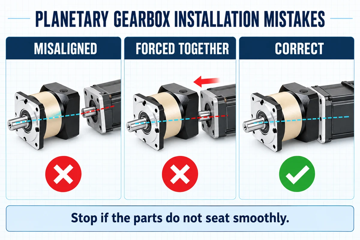
Do not hammer the shaft, strike the housing, lever against the seal or use the flange screws to pull the motor inward. If the motor stops before the faces meet, withdraw it and investigate the shaft length, sleeve, clamp opening, key orientation, pilot fit and alignment. Resistance is evidence; extra force is not a solution.
Steps 7–8: Seat and Tighten the Servo Gearbox Installation
Progressive cross-tightening reduces the chance of drawing one side of the flange down before the opposite side is seated. Use calibrated tools and the fastener torque given for the actual gearbox, adapter and motor combination. Do not copy a torque value from another brand, frame size or screw grade.
The correct order for the motor-flange fasteners and input-clamp screw can be design-specific. Some instructions position the motor, secure the flange and then tighten the clamp; others define a different sequence. The chosen product documentation must decide the sequence. Reinstall the access plug or sealing element after tightening and verify that it is seated correctly. This is one reason a servo gearbox installation should never be completed from memory alone.
Unsure About the Sleeve or Clamping Position?
Send the complete motor model and its dimensional drawing—not only motor power. Include a photo of the gearbox input and the proposed mounting orientation.
Send the Motor Drawing for Review →Steps 9–10: Run the Planetary Gearbox Installation Checks
Keep personnel clear of rotating parts. Confirm the commanded motor direction produces the expected output direction before connecting a process that can jam or collide. Observe sound, vibration, leakage, current, positioning behavior and temperature trend. A new gearbox may have a different acoustic signature from the old unit, but knocking, scraping, repeated torque alarms or rapidly increasing temperature requires investigation.
Do not declare the planetary gearbox installation successful after a few seconds of unloaded rotation. Run a controlled portion of the real cycle, including acceleration, deceleration and reversal where applicable. For a positioning axis, record the initial repeatability or backlash-related result. For a continuous drive, record temperature after a meaningful operating period.
Planetary Gearbox Installation Mistakes and Their Evidence
Most planetary gearbox installation mistakes leave evidence before serious damage occurs: a flange that will not close, a shaft that needs unusual force, fasteners that tighten unevenly or a drive that behaves differently at low speed. Treat those signs as reasons to stop and inspect.
| Installation mistake | Evidence during assembly or startup | Correct response |
|---|---|---|
| Wrong motor adapter or sleeve | Shaft will not enter, clamp contacts the wrong area or pilot does not locate. | Stop and verify motor and gearbox drawings; do not machine parts by guesswork. |
| Contamination or burr on a locating face | Uneven flange gap or motor sits at an angle. | Separate, clean and inspect the mating faces and pilot. |
| Coupling bottoms on the shaft | Flanges cannot meet although shaft diameter appears correct. | Check usable shaft length, bore depth and sleeve position. |
| Bolts used to pull components together | Fastener torque rises while a flange gap remains. | Release the bolts and correct fit or alignment. |
| Uneven or unverified tightening | Misalignment, loosening, noise or movement at the interface. | Use the specified sequence, fastener grade, torque and locking method. |
| No staged commissioning | Direction error, collision, overload alarm or rapid heating appears under load. | Return to low-speed unloaded checks and verify system data. |
Planetary Gearbox Mounting Record for Commissioning
A one-page installation record gives maintenance teams a baseline and helps distinguish installation problems from later process changes. Record the information while it is available, not after an alarm appears.
- Gearbox series, complete model, serial or batch reference and ratio.
- Motor manufacturer, complete model and shaft dimensions.
- Adapter and sleeve identification.
- Mounting orientation and output connection.
- Fastener grade, applied tightening torque and tool calibration status.
- Initial rotation direction and low-speed test result.
- Unloaded motor current, sound or vibration observation and leakage check.
- Temperature and positioning result after the controlled loaded test.
- Installer, date and approved drawing revision.
This record is especially useful when the same machine is built repeatedly. If one unit behaves differently, the installation data provides a starting point before the gearbox is blamed or the servo parameters are changed.
When Planetary Gearbox Installation Needs Manufacturer Review
Request technical review before assembly when the motor drawing is unavailable, the input requires a nonstandard sleeve, the motor is unusually heavy, the installation orientation differs from the approved drawing, the environment requires washdown sealing, or the output carries a substantial pulley, sprocket, pinion or cantilevered load.
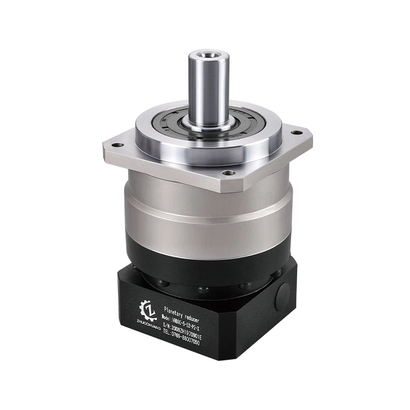
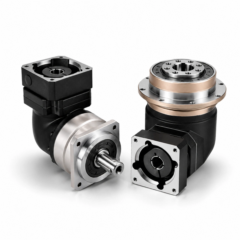
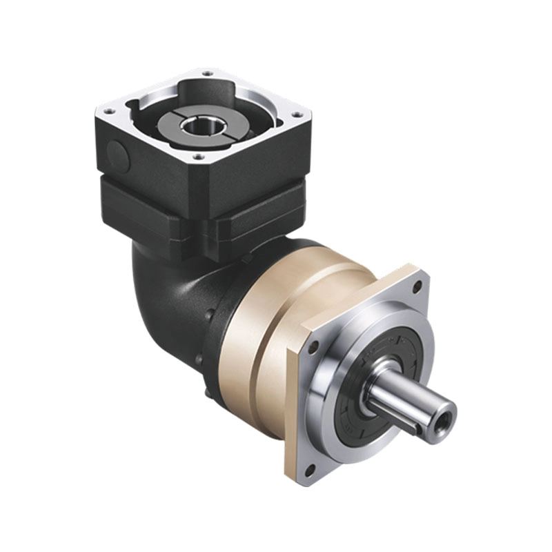
Zhuochuang’s VRB Series inline planetary gearbox uses model coding and motor-interface information that should be confirmed before ordering. For background on matching the motor pilot, shaft and flange, read Planetary Gearbox With Motor. If the machine requires the motor to turn 90 degrees, review the right-angle planetary gearbox range rather than improvising an unsupported mounting arrangement.
For an additional overview of same-axis motor mounting, input bore, motor flange, pilot diameter and bolt-pattern matching, see Inline Planetary Gearbox for Servo Motors on the related planetary-drive.com technical resource site.
Final Planetary Gearbox Installation Release
A good installation leaves no unexplained force, gap or assumption. The motor and gearbox drawings agree; the mating surfaces are clean; the shaft enters without force; the flange seats completely; the correct fasteners are tightened by the model-specific method; and the drive passes a staged commissioning test.
That discipline protects more than the reducer. Correct servo gearbox installation reduces the risk of coupling slip, motor-bearing load, alignment error, unstable positioning and unnecessary troubleshooting. It also gives the buyer a documented starting condition for future maintenance. Avoiding documented planetary gearbox installation mistakes is far less expensive than diagnosing them after the machine reaches the customer.
Request Planetary Gearbox Installation Support
Send the motor model, required ratio, gearbox model, mounting orientation and installation drawing. For a new project, also include torque, speed, duty cycle, backlash target and output-load details.
Submit Motor Data and Request a Review →