
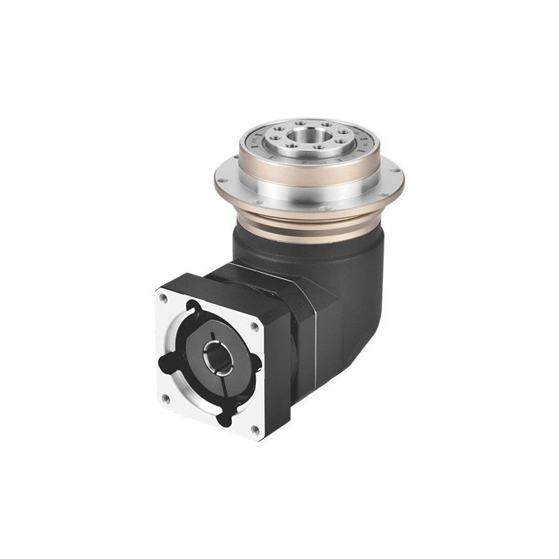
Precision Helical Gears & Custom Helical Gear Manufacturing
Custom helical gears, precision pinions and machined gear shafts for industrial gearboxes, machinery and OEM power transmission projects.
Dongguan Zhuochuang Precision Machinery Co., Ltd. supplies precision transmission products and supports custom helical gear manufacturing based on customer drawings, gear geometry and application requirements.
From replacement helical gears to matched gear pairs and integrated pinion shafts, we help industrial equipment manufacturers evaluate materials, tooth accuracy, mechanical interfaces and production feasibility before quotation.
What Are Helical Gears and Why Are They Used?
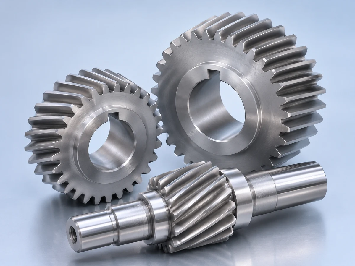
Helical gears are cylindrical gears with teeth inclined at a helix angle relative to the gear axis. Unlike straight-cut spur gears, helical gear teeth engage progressively along the tooth face. This gradual engagement can provide smoother torque transmission and reduced vibration when the gear pair is correctly designed and installed.
Precision helical gears are commonly selected for industrial speed reducers, enclosed gearboxes, automation machinery and other applications where stable power transmission is important.
Smooth Tooth Contact
The angled teeth progressively enter and leave mesh, helping distribute transmitted load over the engagement cycle.
Industrial Torque Transfer
Properly designed helical gear sets can transmit substantial torque in compact gearbox arrangements.
Vibration and Noise Control
Suitable tooth geometry, alignment and finishing can reduce transmission vibration and operating noise.
Engineering consideration: Helical gears generate axial thrust during operation. Bearing selection, shaft support and the direction of the helix must therefore be included in the transmission design.
Custom Cylindrical Helical Gears for Parallel-Shaft Drives
Cylindrical helical gears are widely used in parallel-shaft gearboxes, industrial speed reducers, transmission equipment and automated machinery.
Our custom helical gear supply can be evaluated for different tooth counts, modules, face widths, bore dimensions, mounting requirements and operating loads.
For a typical external parallel-shaft gear pair, the driving and driven gears require compatible tooth geometry and opposite helix hands. The corresponding helix angles must have the same magnitude for correct meshing.
A replacement helical gear should therefore not be selected only by its outside diameter or number of teeth. Normal module, pressure angle, helix direction, profile modification and center distance must also be considered.
Helical Gear Design: Module, Helix Angle and Tooth Geometry
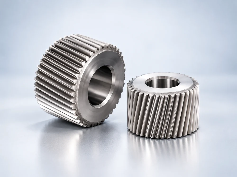
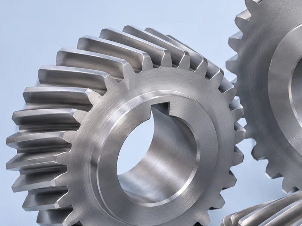
The performance of precision helical gears depends on accurately defined tooth geometry. Critical parameters include normal module, tooth count, pressure angle, helix angle, face width, profile shift and the specified center distance.
The normal module and transverse module are different quantities in a helical gear design. Confusing them can cause incorrect pitch diameter calculations and unsuitable mating parts.
The helix angle also affects the axial force acting on a gearbox shaft. Gear design must therefore consider both the required torque transmission and the available bearing support.
For OEM and replacement helical gear projects, we recommend providing the mating gear drawing or relevant assembly information whenever possible.
Design relationship: For a conventional helical gear, transverse module = normal module / cos(helix angle). The selected calculation system and all tooth parameters should be explicitly identified on the engineering drawing.
Custom Helical Gear Manufacturing Specifications
Each custom helical gear is reviewed against its intended application and customer drawing. The following parameters help define a suitable manufacturing and inspection scope.
| Parameter | Engineering Requirement | Importance |
|---|---|---|
| Gear Type | External helical gear, pinion, integrated gear shaft or matched gear set | Defines transmission configuration |
| Module | Normal or transverse module, clearly specified | Controls tooth sizing and compatibility |
| Number of Teeth | Specified for each mating gear | Determines ratio and geometry |
| Helix Angle | Angle and left-hand or right-hand direction | Affects gear mesh and axial thrust |
| Pressure Angle | Normal or transverse pressure angle | Required for compatible engagement |
| Face Width | Working tooth width according to load and installation | Influences load distribution |
| Material | Selected alloy steel or other approved material | Determines mechanical and thermal properties |
| Heat Treatment | Carburizing, quenching, tempering or nitriding where appropriate | Controls hardness and wear resistance |
| Accuracy | Specified ISO 1328 or other applicable gear accuracy requirements | Defines tooth quality and inspection targets |
| Machined Interfaces | Bore, keyway, spline, bearing seat, shoulders and threads | Supports correct assembly |
Important: This table describes specification categories, not fixed standard capabilities. Available materials, dimensions, tooth accuracy and processing methods are confirmed after drawing and manufacturing feasibility review.
Helical Gear Machining and Manufacturing Process
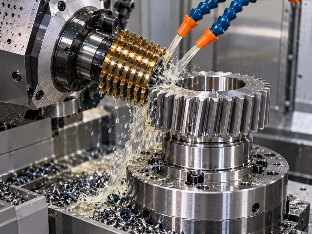
Custom helical gear manufacturing combines precision blank machining, tooth generation, material treatment and dimensional verification. The manufacturing route depends on gear geometry, production quantity and quality requirements.
Drawing-Based Helical Gear Production
Zhuochuang supports industrial gear projects from drawing review through manufacturing coordination and finished-part supply. Specialized gear machining operations are arranged according to the approved technical requirements.
CNC turning can be used to prepare gear blanks, bores and locating surfaces. Gear hobbing is a common method for generating external helical gear teeth, while other gear cutting methods may be selected for special geometries.
Depending on the material and service requirements, production may include heat treatment, tooth finishing, gear grinding and final inspection.
For precision helical gear manufacturing, the objective is not simply to produce the correct overall shape. Tooth profile, lead accuracy, runout, gear mounting interfaces and the relationship between mating components must be controlled according to the drawing.
From Helical Gear Drawings to Finished Components
A structured manufacturing workflow helps equipment manufacturers reduce specification errors and improve component compatibility.
Drawing Review
Examine the 2D drawing, 3D model, tooth parameters, material and mating requirements.
Process Planning
Evaluate blank preparation, gear tooth generation, heat treatment and finishing requirements.
Gear Manufacturing
Arrange the approved machining processes and coordinate critical dimensional requirements.
Inspection and Delivery
Confirm agreed inspection criteria, packaging, delivery conditions and order documentation.
For repeat OEM orders, retaining the approved gear drawings, material requirements and inspection criteria helps maintain consistency between production batches.
Custom Helical Gear Shafts and Precision Pinions
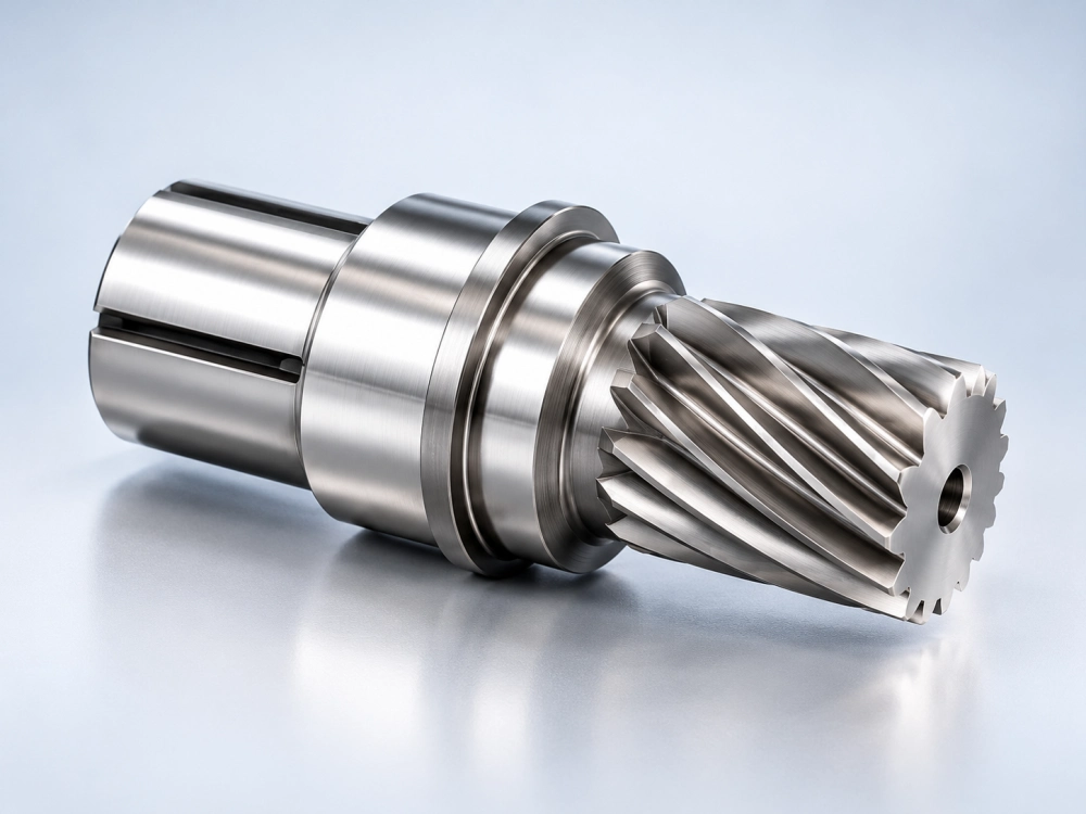
Some industrial applications require an individual helical gear mounted onto a shaft, while others use an integrated gear shaft with the gear teeth machined directly into the shaft component.
Custom helical gear shafts may include bearing seats, splines, keyways, stepped diameters, threaded sections and other connection features.
These features are important because concentricity, shaft runout and the position of the gear teeth relative to the bearing surfaces can affect the complete gearbox assembly.
Our team can evaluate drawing-based manufacturing requests for individual helical pinions, integrated gear shafts and compatible transmission components.
Customers can send both gear and shaft drawings for a combined manufacturability review, reducing the risk of mismatched mechanical interfaces.
Material Selection for Precision Helical Gears
Material selection should be based on the operating load, required fatigue life, wear resistance, lubrication conditions, production quantity and specified heat treatment.
Alloy Steel Helical Gears
Alloy steels such as 20CrMnTi and 18CrNiMo7-6 may be evaluated for applications requiring case hardening and suitable core strength. Material selection depends on the applicable standard and design.
Medium-Carbon Steel Gears
Materials such as 45 steel or 42CrMo may be considered for selected gear applications, depending on mechanical strength, operating loads and heat-treatment requirements.
Special Gear Materials
Stainless steel and other specialized materials may be evaluated for applications with particular environmental, corrosion-resistance or operating requirements.
Helical Gear Heat Treatment and Tooth Finishing
Heat treatment can improve hardness and wear performance, but it may also affect gear dimensions and tooth geometry. The order of machining, heat treatment and finishing must therefore be planned carefully.
Depending on the approved specification, a helical gear may require carburizing, quenching, tempering, nitriding or a suitable finishing process. Gear grinding may be necessary where tighter tooth accuracy or surface requirements are specified.
The required material certificate, hardness range, heat-treatment record and inspection report should be agreed upon before production rather than assumed to be included with every order.
Precision Helical Gear Inspection and Quality Requirements
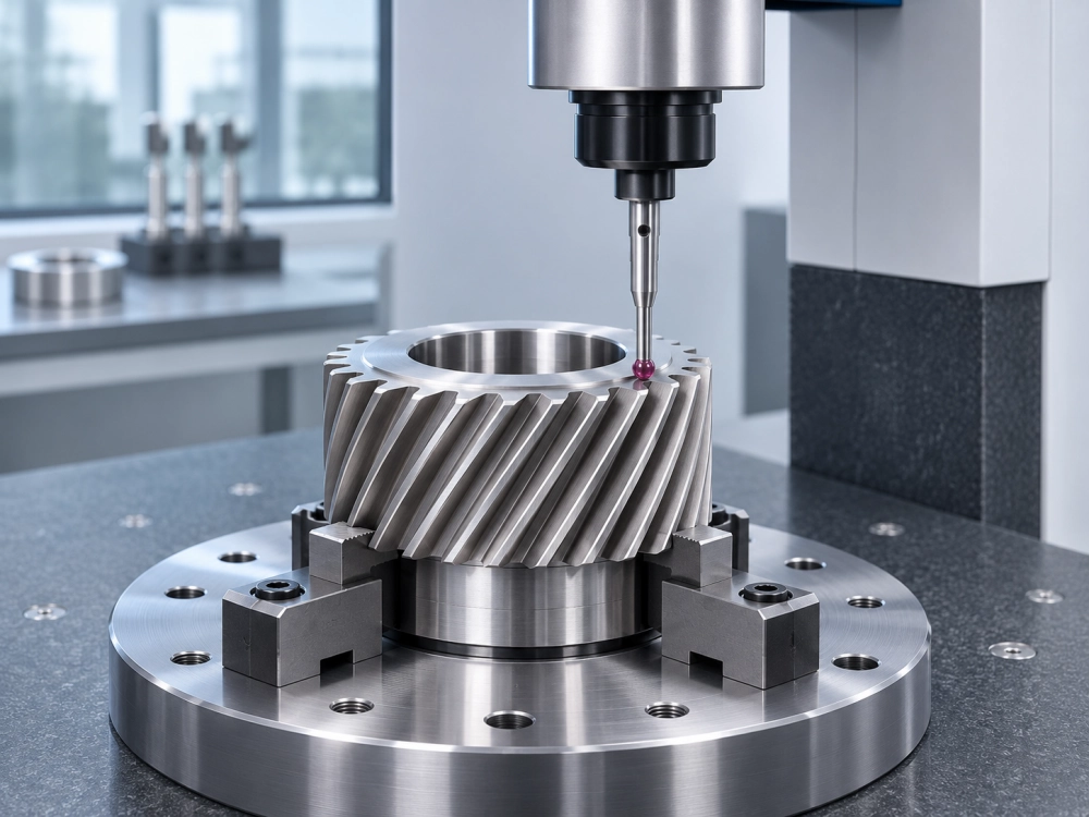
Precision helical gear inspection is important for confirming tooth geometry, dimensional accuracy and compatibility with the intended transmission assembly.
Depending on the drawing, inspection requirements may include tooth profile deviation, helix or lead deviation, pitch variation, radial runout, tooth thickness and bore concentricity.
Gear inspection methods can include suitable gear measuring equipment, coordinate measuring machines and dedicated dimensional measuring instruments.
Customers may specify gear accuracy requirements using ISO 1328 or other appropriate standards. A gear accuracy grade is meaningful only when its applicable standard, measured parameters and acceptance criteria are clearly defined.
For helical gear manufacturing projects, Zhuochuang coordinates required inspection expectations with the selected production resources. Specific test methods and documentation are confirmed as part of the order review.
Helical Gears for Industrial Gearboxes and Machinery
Precision helical gears are used in mechanical systems where reliable power transfer, controlled gear engagement and suitable load capacity are essential.
Industrial Speed Reducers
Helical gear pairs are frequently used in enclosed reduction systems that require stable torque transmission and continuous mechanical operation.
Automation Equipment
Custom gear shafts and precision helical gears can support machine drives, automated equipment and specialized motion transmission assemblies.
CNC and Machine Tools
Suitable transmission gears may be used in machine-tool drive mechanisms and related auxiliary motion systems.
Packaging Machinery
Gear-based mechanical drives can transmit motion between rotating shafts in packaging and material-handling systems.
OEM Gearbox Assemblies
Equipment manufacturers may need custom gear pairs, pinions and shafts for new gearbox development or replacement projects.
Precision Transmission Projects
Drawing-based helical gears can be evaluated for specialized industrial equipment that requires nonstandard dimensions or mechanical interfaces.
Custom Helical Gears Based on Drawings or Existing Samples
Replacing a damaged helical gear is not always a straightforward dimensional matching exercise. A visually similar component may differ in tooth profile, helix angle, heat treatment or machining accuracy.
For OEM projects, we recommend submitting complete 2D drawings, STEP files, material requirements and information about the intended gear mesh.
For replacement gear requests without original drawings, photographs and physical samples may support an initial review. Additional measurement or reverse engineering may be necessary before manufacturing compatibility can be assessed.
When the original tooth geometry is uncertain or both mating gears are worn, evaluation of the complete gear pair may be more appropriate than replacing only one component.
Information to Include in Your RFQ
- Gear type and application
- 2D technical drawing or STEP file
- Normal module and number of teeth
- Helix angle and helix direction
- Pressure angle and face width
- Material and required heat treatment
- Gear accuracy or dimensional tolerances
- Required quantity and delivery destination
If some technical information is unavailable, send the existing part photographs and the known equipment details for an initial engineering review.
Helical Gears vs. Spur Gears: Which Is Suitable?
Helical gears and spur gears can both transmit power between parallel shafts, but their tooth geometry, engagement behavior and supporting design requirements differ. For straight-tooth designs, review our custom spur gears page.
| Comparison | Helical Gears | Spur Gears |
|---|---|---|
| Tooth Direction | Inclined relative to the gear axis | Parallel to the gear axis |
| Tooth Engagement | Progressive engagement | More simultaneous engagement across face width |
| Noise and Vibration | Can provide smoother, quieter operation | May be suitable for simpler or lower-speed systems |
| Axial Thrust | Axial thrust must be considered | No nominal axial thrust from ideal straight-tooth engagement |
| Manufacturing | Helical tooth geometry requires suitable tooling and setup | Straight teeth can simplify certain manufacturing operations |
| Typical Selection | Industrial reducers and smoother transmission requirements | General parallel-shaft mechanical drives |
The appropriate gear type depends on torque, speed, available space, manufacturing requirements, bearings, lubrication and the complete transmission design. Neither type should be selected based on noise or load capacity alone.
Explore More Gear and Drive Solutions
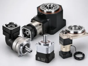
Besides custom helical gear manufacturing, Zhuochuang supplies precision transmission assemblies and can evaluate selected gear components for OEM machinery projects.
Precision Gears
Explore our precision gear categories including helical gears, internal ring gears, planetary gear components and custom machined parts.
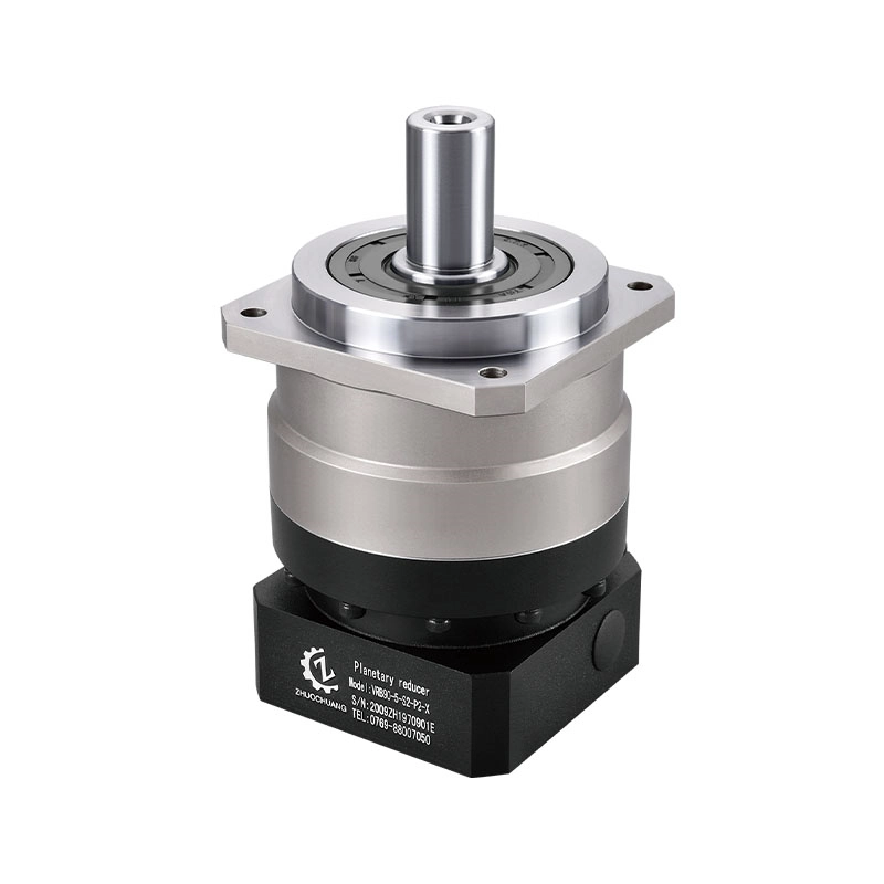
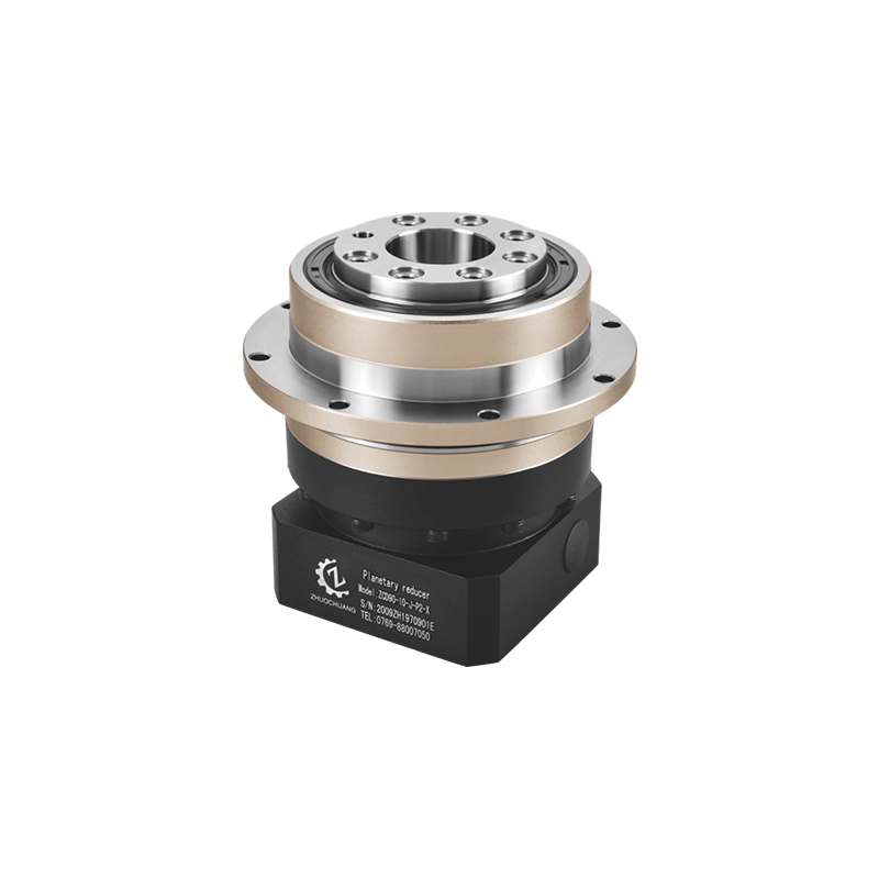
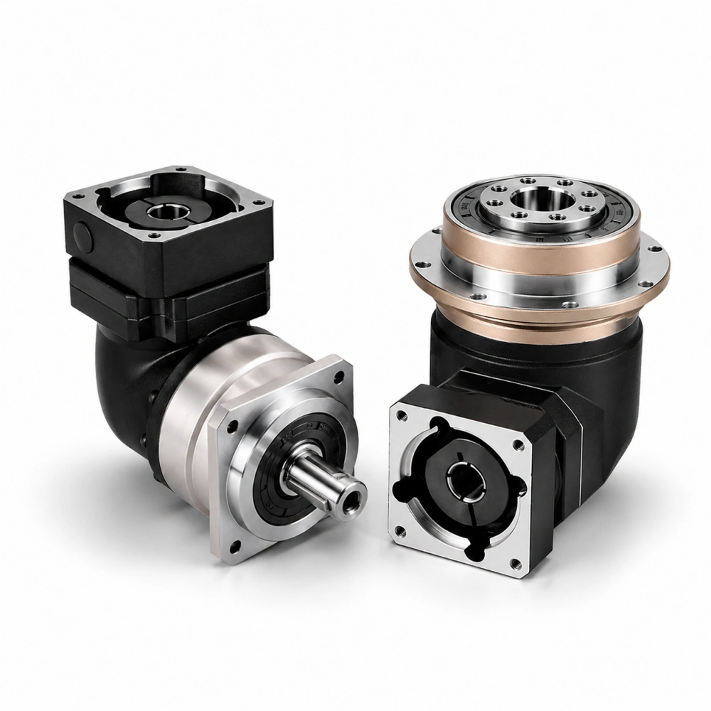
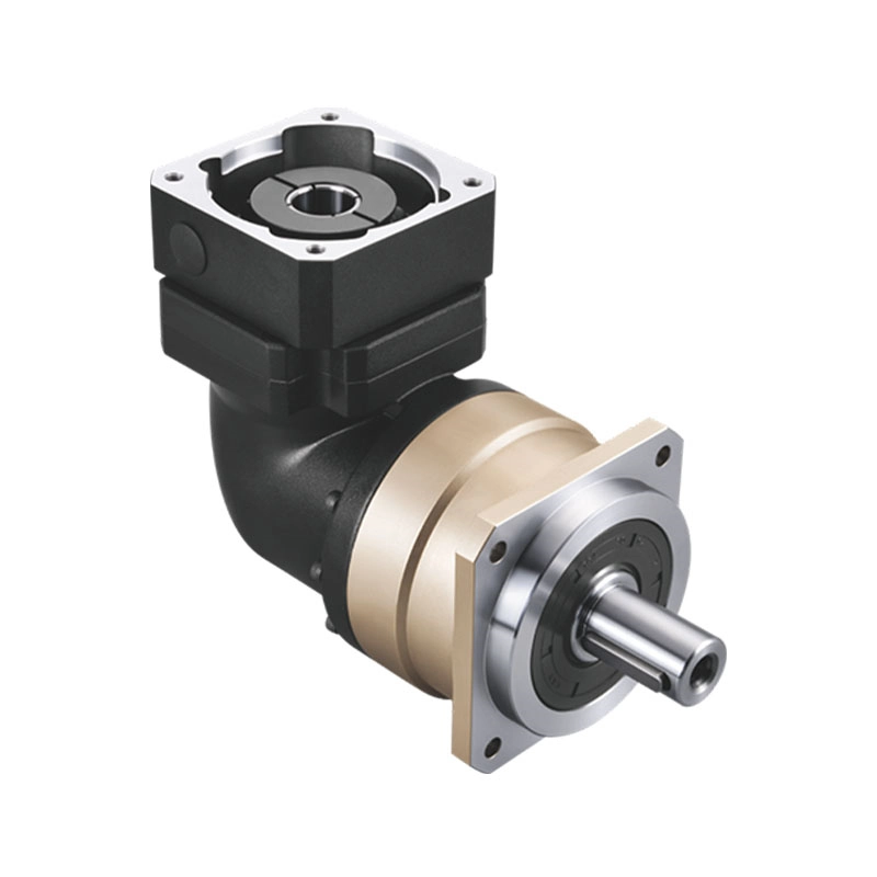
Planetary Gearboxes
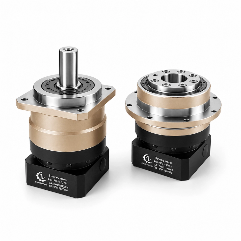
Complete inline and right-angle planetary gearboxes for servo motors, automation equipment and industrial motion systems.
Hollow Rotary Tables
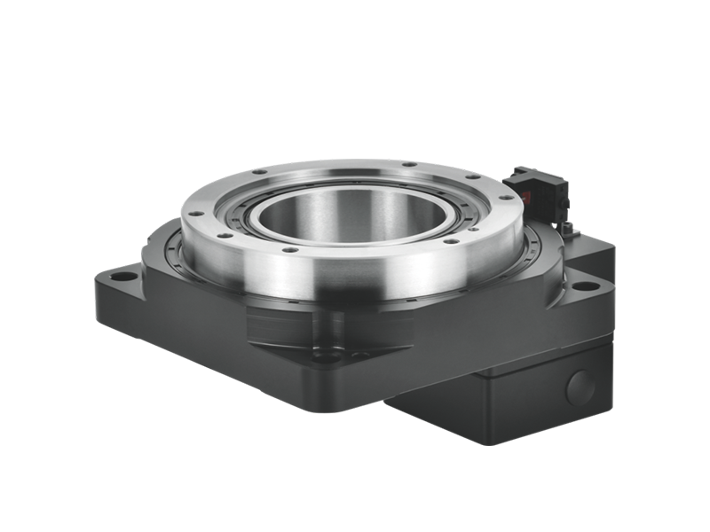
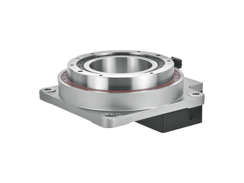
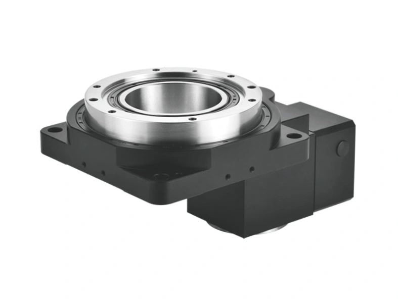
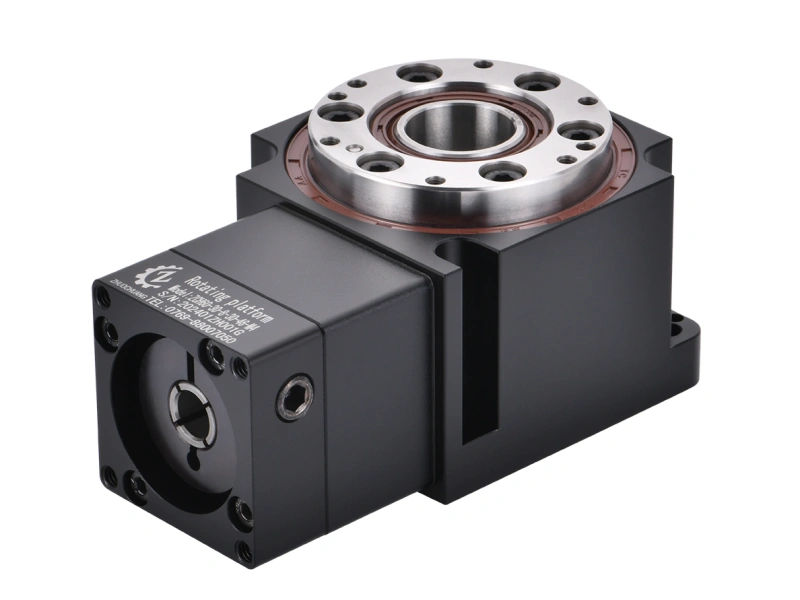
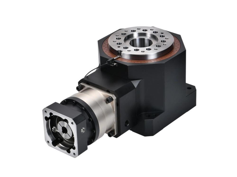
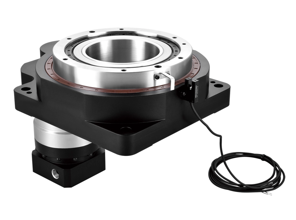
Precision hollow rotary tables for rotary indexing, equipment positioning and automated machinery applications.
Custom Helical Gear Manufacturing FAQs
What is a helical gear?
A helical gear is a cylindrical gear with teeth inclined at an angle to its axis. This tooth geometry provides progressive engagement and is commonly used in industrial power transmission.
Can you manufacture custom helical gears from drawings?
Yes. Zhuochuang evaluates custom helical gear manufacturing requirements using customer drawings, gear geometry, material specifications, quantities and application details. Final manufacturing scope is confirmed after technical review.
What information is needed for a helical gear quotation?
A technical drawing or STEP model is preferred. Important specifications include normal module, tooth count, pressure angle, helix angle, helix direction, face width, material, heat treatment, accuracy requirements and quantity.
Can helical gears be used in planetary gearboxes?
Yes. Some planetary gearbox designs use helical gears for the sun and planet gears. Such systems require compatible internal ring gear geometry and appropriate consideration of axial loading and assembly conditions.
Can you supply helical pinion shafts?
Custom helical gear shafts and pinions may be evaluated against supplied drawings. These can include integrated teeth, bearing seats, splines, keyways and other machined connection features.
What materials are used for precision helical gears?
Alloy steels and other engineering materials may be selected depending on load, fatigue resistance, wear requirements and heat treatment. Exact material grades are determined by the approved design.
What gear accuracy grades are available?
Required accuracy is reviewed against the specified gear standard, such as ISO 1328, and the actual geometry and inspection scope. No universal accuracy grade is guaranteed for every custom order.
Can you manufacture a replacement helical gear from a sample?
A physical sample may support an initial assessment, but the original module, helix angle, tooth modifications, material and manufacturing tolerances may require additional verification before production.
Are helical gears and spiral bevel gears the same?
No. Cylindrical helical gears are commonly used for parallel-shaft transmission. Spiral bevel gears use conical gear geometry and are commonly used to transmit motion between intersecting shafts. The two should be treated as separate product categories.
Need Custom Helical Gears for Your Industrial Project?
Whether you need precision helical gears, a replacement gear pair, a machined pinion shaft or an OEM gear component, our team can review your technical requirements and discuss the available manufacturing options.
Share your drawings, gear geometry, application information and required quantity to begin the quotation process.
What to Include in Your Inquiry
- 2D technical drawing or 3D STEP file
- Gear type, tooth count and module
- Helix angle, pressure angle and face width
- Required material and heat treatment
- Accuracy, tolerance and inspection requirements
- Quantity, shipping destination and target schedule
Dongguan Zhuochuang Precision Machinery Co., Ltd.
ZCJER / PlanetDrivePro
Dongguan, Guangdong, China
Email: info@planetdrivepro.com