
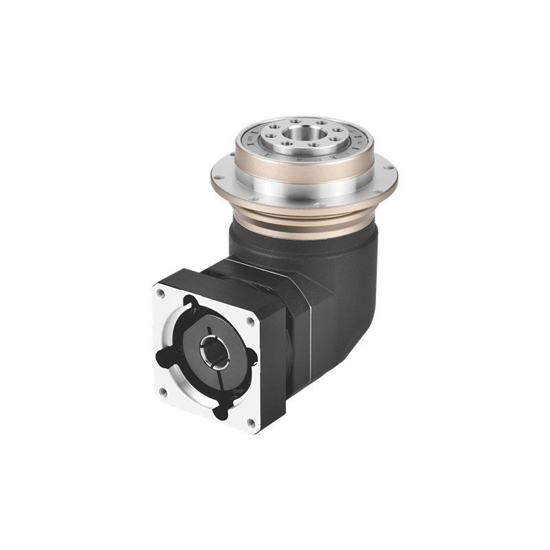
Custom Spur Gears & Precision Spur Gear Manufacturing
Drawing-based custom spur gears, precision steel gears and straight-cut gear components for industrial OEM equipment and mechanical power transmission.
Dongguan Zhuochuang Precision Machinery Co., Ltd. supports custom spur gear manufacturing projects for equipment builders, mechanical transmission manufacturers and industrial maintenance applications.
From individual metric spur gears to matched gear-and-pinion sets, we review tooth geometry, materials, dimensions, mounting interfaces and inspection requirements before coordinating production.
Whether you need a replacement steel spur gear or a new OEM transmission component, send us your technical drawing for a manufacturing feasibility review and quotation.
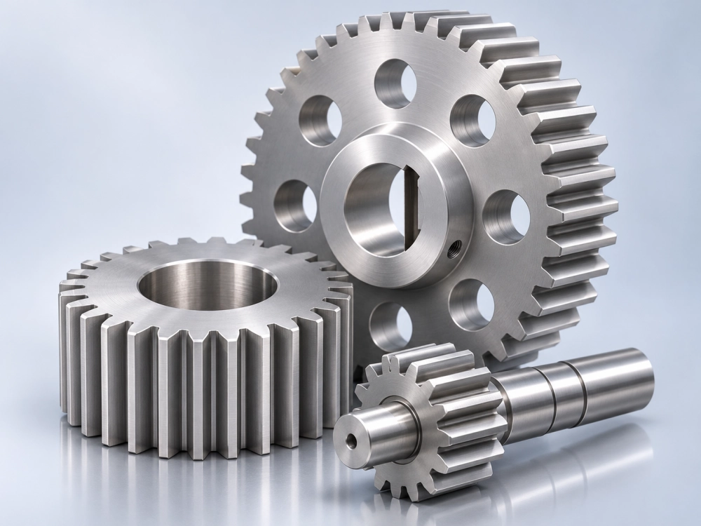
What Are Spur Gears and How Do They Work?
Spur gears are cylindrical gears with straight teeth arranged parallel to their rotation axis. Two external spur gears can mesh together to transmit rotary motion and torque between parallel shafts.
The speed ratio of a simple external gear pair is determined by the number of teeth on the driving and driven gears. Their tooth geometry must be compatible to maintain correct engagement.
Straight Tooth Geometry
Unlike cylindrical helical gears, spur gear teeth are parallel to the gear axis. This geometry makes spur gears suitable for many conventional parallel-shaft arrangements.
Predictable Gear Ratios
Gear ratios can be determined from the selected tooth counts. Correct module, pressure angle, shaft alignment and center distance are essential for proper operation.
Custom Industrial Designs
Spur gears may include plain bores, keyed hubs, mounting holes, integral shafts and other mechanical interfaces according to the customer’s drawing.
Custom spur gears are commonly selected where engineers need an established cylindrical gearing arrangement and drawing-specific dimensions. Actual noise, load capacity, backlash and service life depend on gear design, manufacturing quality, lubrication and operating conditions.
Custom Spur Gear Types for Industrial Equipment
Custom spur gears are not limited to one diameter, tooth count or mounting configuration. Their dimensions and connection features are designed for the surrounding transmission.
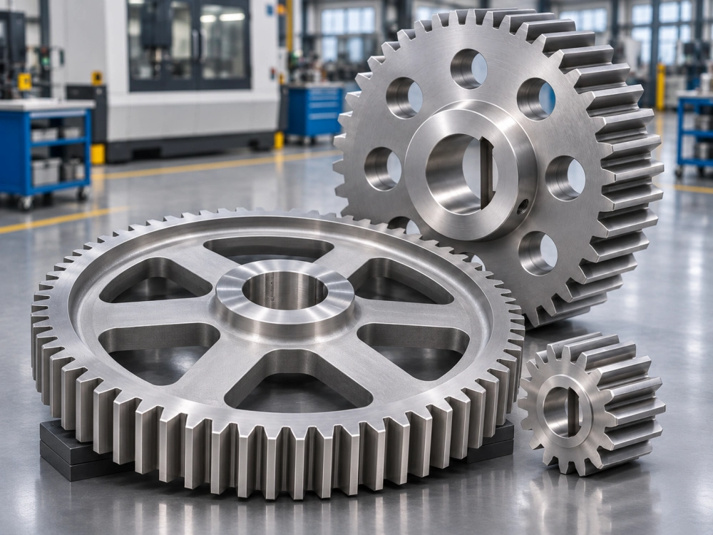
We evaluate precision spur gears from customer drawings, including compact pinions, larger steel spur gears, gear wheels and components with integrated hubs or shafts.
For an existing gearbox, the replacement gear must also be compatible with its mating gear and mounting arrangement.
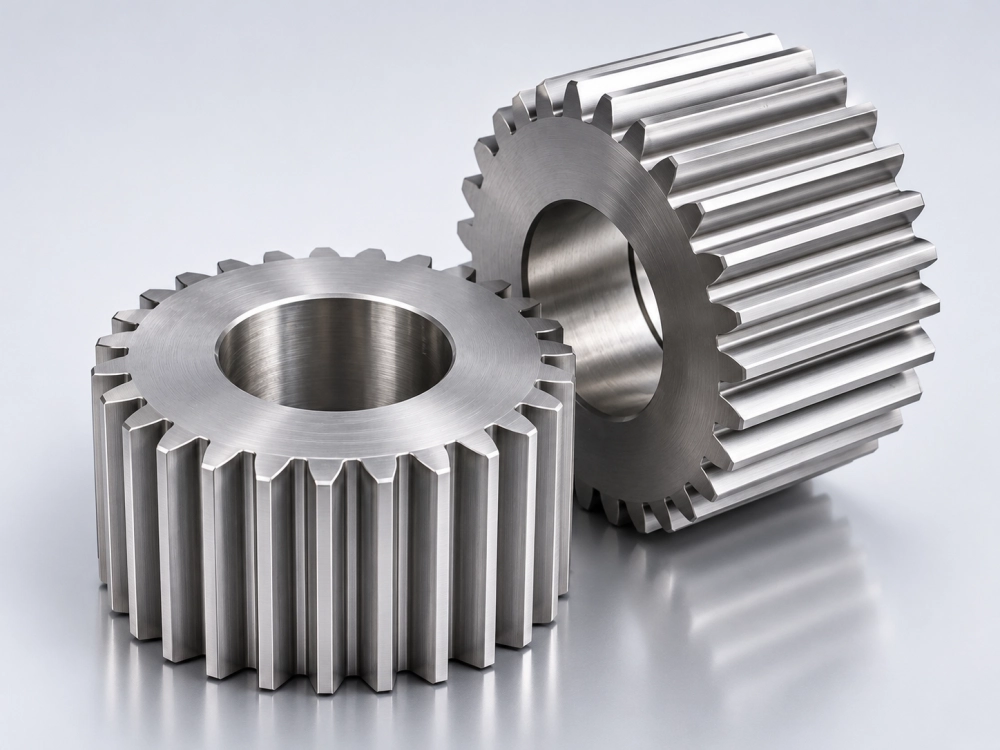
Plain Spur Gears
Cylindrical gears with straight external teeth, machined to the specified bore and face width.
Hub Spur Gears
Gears with extended hubs, keyed bores or mounting features for connection to the transmission shaft.
Spur Pinion Gears
Smaller driving or driven gears, sometimes integrated with a shaft for compact mechanical transmissions.
Custom Gear Wheels
Larger spur gear wheels with selected spokes, lightening holes, flanges and mounting interfaces.
Metric Spur Gears: Module, Tooth Count and Pressure Angle
Metric spur gears are commonly defined by their module, number of teeth and pressure angle. These basic parameters establish the reference tooth geometry.
Module represents the tooth size in the metric system. A larger module generally produces larger teeth for the same tooth count.
The number of teeth influences the reference diameter and transmission ratio. Pressure angle influences tooth contact geometry and the resulting forces in the gear mesh.
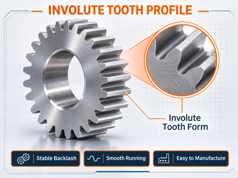
A 20-degree pressure angle is common in standard involute spur gear designs. However, replacement gears may use other pressure angles, profile modifications or non-standard geometry.
Our team reviews the complete design rather than assuming every metric spur gear follows one standard profile.
| Design Parameter | Technical Meaning | Information for RFQ |
|---|---|---|
| Module (m) | Metric tooth-size parameter | Specify module or provide a complete tooth drawing |
| Number of Teeth (z) | Influences gear diameter and speed ratio | Give exact tooth count for each mating gear |
| Pressure Angle | Defines the direction of tooth contact force | State the required angle and tooth system |
| Face Width | Axial width of the gear tooth engagement | Provide width and tolerance on the drawing |
| Bore / Hub | Mechanical connection to the shaft | Specify diameter, keyway, fit and mounting details |
| Tooth Accuracy | Controls selected tooth geometry deviations | Specify the applicable standard and accuracy grade |
Spur Gear Center Distance and Gear Ratio Calculation
A simple calculation helps engineers check a preliminary spur gear pair layout. For standard external metric spur gears without profile shift, the reference pitch diameter is determined by the module and tooth count.
Reference Pitch Diameter: d = m × z
Standard Center Distance: a = m × (z1 + z2) / 2
Gear Ratio Magnitude: i = z2 / z1
Example: A Module 2 Spur Gear Pair
Consider an illustrative gear pair with a 20-tooth pinion driving a 40-tooth gear. Both gears use module 2 and standard unshifted external tooth geometry.
| Parameter | Driving Pinion | Driven Gear |
|---|---|---|
| Module | 2 mm | 2 mm |
| Tooth Count | 20 | 40 |
| Reference Diameter | 40 mm | 80 mm |
| Standard Outside Diameter | 44 mm | 84 mm |
| Center Distance | 60 mm | |
| Ratio Magnitude | 2:1 | |
In this example, the driven gear rotates at half the driving pinion’s speed, and the two external gears rotate in opposite directions.
This calculation is only a preliminary reference. Profile shift, backlash, tolerance, working center distance and detailed tooth modifications may change the final geometry.
Custom Spur Gear Manufacturing from Drawing to Finished Component
Custom spur gear manufacturing involves more than cutting straight teeth into a metal blank. The production route must consider material condition, hub geometry, machining allowances, heat treatment and required tooth accuracy.
Dongguan Zhuochuang Precision Machinery Co., Ltd. supports drawing-based gear manufacturing projects by reviewing specifications and coordinating suitable external machining resources.
Depending on the approved design, relevant processes may include CNC turning, milling, spur gear hobbing, gear shaping, heat treatment, tooth finishing and dimensional inspection.
Spur gear hobbing is widely used for generating external involute teeth. Other operations are selected according to the complete part geometry and required manufacturing results.
For a custom spur gear with a keyway, stepped hub or integral shaft, the tooth machining operation must be coordinated with the remaining precision features.
How a Custom Spur Gear Manufacturing Project Is Reviewed
A structured engineering review helps reduce misunderstandings about tooth geometry, fitting dimensions and acceptance requirements before production.
Check tooth geometry, dimensions, bore, shaft connection, tolerances and quantities.
Evaluate material grades, hardness targets, operating loads and heat treatment.
Determine suitable blank machining, tooth generation and finishing methods.
Agree on dimensional checks, gear accuracy requirements and inspection documentation.
Manufacturing capabilities, delivery conditions and the inspection scope are confirmed for each project before order acceptance. The selected production route depends on the drawing, quantity and available resources.
Steel Spur Gears and Custom Material Selection
Material selection affects the load capability, wear behavior and production route of custom spur gears. The appropriate material depends on the mechanical application rather than a single universal recommendation.
| Material Category | Typical Considerations | Project Review |
|---|---|---|
| Medium-Carbon Steel | General-purpose machined components and selected moderate-duty applications | Load, hardness, surface finish and heat treatment |
| Alloy Steel | Applications needing specified mechanical properties and fatigue performance | Material grade, heat treatment, hardness profile |
| Case-Hardening Steel | Applications requiring a hard tooth surface and suitable core properties | Case depth, hardness, distortion and finishing |
| Stainless Steel | Selected corrosion-sensitive environments | Specific grade, load requirements and manufacturability |
| Brass / Other Alloys | Selected low-load or specialty transmission designs | Application suitability, wear and mating material |
For steel spur gears, selected projects may require quenching and tempering, carburizing, nitriding or other specified treatment. The correct sequence of machining and heat treatment must also consider possible dimensional distortion.
We review the customer’s required material standard and treatment conditions before confirming the manufacturing scope. Material availability and process capability are subject to project confirmation.
Precision Spur Gear Inspection and Dimensional Quality Requirements
Precision spur gears require the appropriate control of tooth geometry and machined mechanical interfaces. An accurate tooth profile alone is insufficient if the bore, hub or mounting dimensions do not fit the assembly.
Tooth Geometry
Inspection requirements may include tooth profile, pitch deviation, lead or tooth alignment, runout and related gear accuracy parameters.
Mounting Dimensions
Bores, keyways, outside diameters, shoulders, mounting holes and concentricity are checked according to the drawing.
Material Conditions
Material identification, hardness and selected surface or heat-treatment conditions may be included in the agreed scope.
Inspection methods depend on the required gear accuracy, available measuring equipment and manufacturing process. The applicable standard, tolerance values and reporting requirements should be established before production.
For replacement spur gears, the condition of the mating component is also relevant. New replacement teeth may not engage correctly with a severely worn or incompatible gear.
Precision Spur Gears for Industrial Machinery
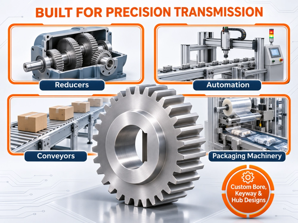
Spur gears are used in mechanical transmissions where parallel shafts transfer rotational motion and torque. The suitable arrangement depends on equipment geometry, load and operating conditions.
Selected applications include industrial reducers, automated production machinery, conveyor drives, mechanical indexing systems, actuators and OEM transmission assemblies.
Custom spur gear projects may involve replacement parts for existing machines or newly developed motion systems.
Our project review connects custom gear geometry with the surrounding shaft, bearing, housing and transmission design.
Spur Gear and Rack Transmission Applications
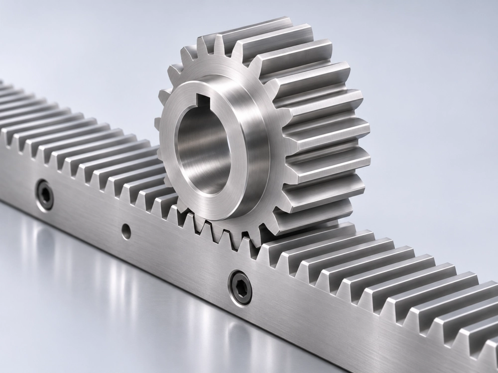
A spur-type pinion can mesh with a straight-tooth gear rack to convert rotary motion into linear motion. This differs from a conventional two-gear rotary transmission.
Rack and pinion mechanisms may be found in linear positioning, machinery adjustment, material handling and industrial motion-control systems.
For compatible rack-and-pinion components, the pinion module, pressure angle, tooth geometry, mounting and operating conditions must match the rack design.
Selected rack and pinion requirements may be reviewed as custom transmission component projects.
Spur Gears vs Helical Gears: Which Is Suitable?
Spur gears and cylindrical helical gears can both transmit power between parallel shafts, but their tooth geometry produces different engagement characteristics.
| Feature | Spur Gear | Helical Gear |
|---|---|---|
| Tooth Direction | Parallel to gear axis | Inclined to gear axis |
| Typical Shaft Arrangement | Parallel shafts | Parallel shafts for cylindrical helical gear pairs |
| Tooth Engagement | More abrupt engagement across the tooth face | More progressive tooth engagement |
| Axial Thrust | No inherent axial thrust from ideal straight tooth geometry | Generates axial thrust during torque transmission |
| Manufacturing | Commonly simpler tooth geometry | Additional helix-angle considerations |
A helical gear may be preferred when smoother tooth engagement is especially important, while a spur gear may suit applications requiring simpler parallel-shaft geometry. Final selection depends on torque, speed, noise, bearings, packaging and cost requirements.
For detailed helical gear design and manufacturing, explore our separate Precision Helical Gears product page.
What Information Is Required for a Custom Spur Gear Quotation?
A complete drawing package helps us evaluate custom spur gears more efficiently. Buyers should provide the following information where available.
Gear Geometry
Module or diametral pitch, number of teeth, pressure angle, face width, bore dimensions and mating gear information.
Production Requirements
Material grade, heat treatment, hardness, tolerances, surface finish and applicable inspection criteria.
Commercial Details
Required quantity, prototype or production status, delivery destination, target schedule and relevant packaging requirements.
PDF drawings and STEP files are particularly useful. If a drawing is unavailable, photographs and a physical sample may support an initial assessment, but additional technical measurements may be needed before production.
For a replacement gear, please also provide the original equipment model and available mating-part information. This can help identify compatibility requirements that are not visible from a photograph.
Custom Spur Gear Manufacturing FAQs
Practical answers for engineers and industrial buyers sourcing custom spur gear components.
What is a spur gear?
A spur gear is a cylindrical gear with teeth parallel to its axis. External spur gears commonly transmit rotary motion between parallel shafts.
Can you manufacture custom spur gears from drawings?
We support drawing-based custom spur gear projects through technical review and suitable manufacturing resources. Production feasibility is confirmed according to gear geometry, material, quantity and accuracy requirements.
What is the difference between metric spur gears and inch gears?
Metric spur gears are generally specified by module, while inch-system spur gears are commonly specified by diametral pitch. Their tooth geometry must be compatible for correct engagement.
What material is suitable for steel spur gears?
Suitable materials depend on torque, loading, wear, lubrication and environmental conditions. Carbon steel, alloy steel and selected case-hardening steels may be evaluated according to the drawing.
How is the center distance of two spur gears calculated?
For a standard unshifted external metric gear pair, the reference center distance is module multiplied by the sum of the two tooth counts, divided by two. Profile shifts and operating geometry may alter the actual working distance.
Can spur gears be used in planetary gearboxes?
Yes. Planetary gear transmissions may use straight-tooth sun and planet gears. The complete arrangement also involves an internal ring gear and planet carrier. The selected design determines the geometry.
Can you make a replacement spur gear from a sample?
An existing part can support an initial engineering review. However, a sample may not reveal its original material, hardness, tooth modifications or design tolerances. Further inspection or technical information may be necessary.
Do you supply complete planetary gearboxes as well?
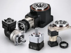
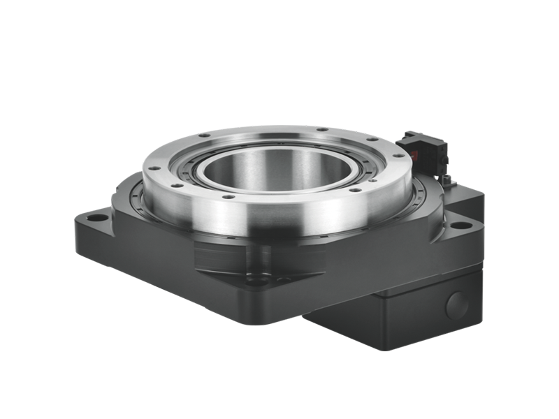
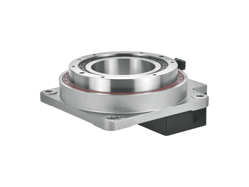
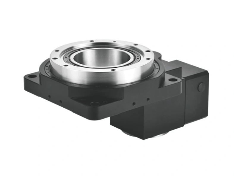
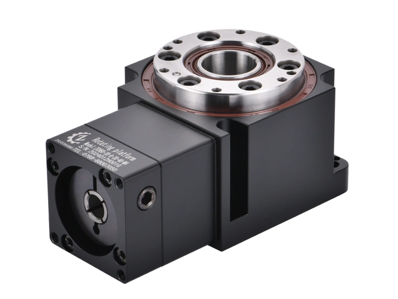
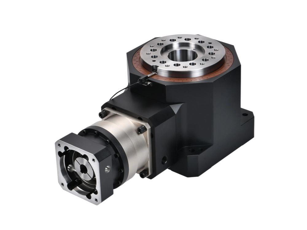
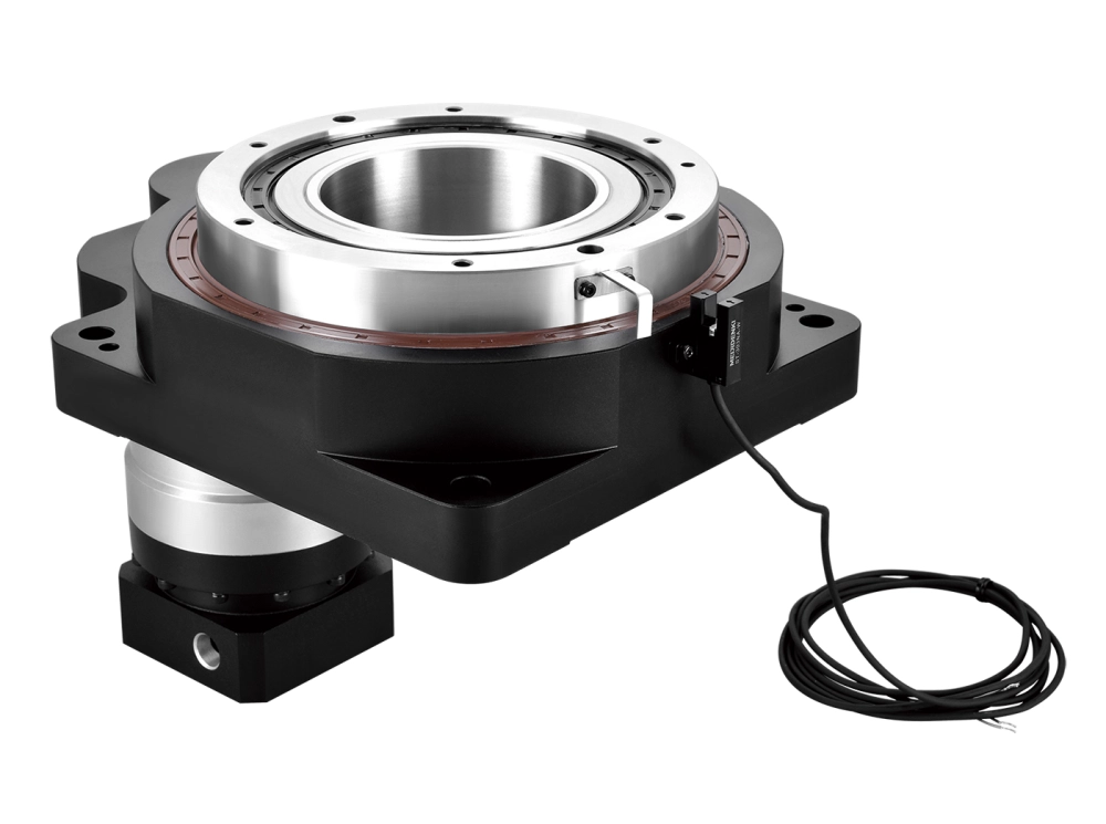
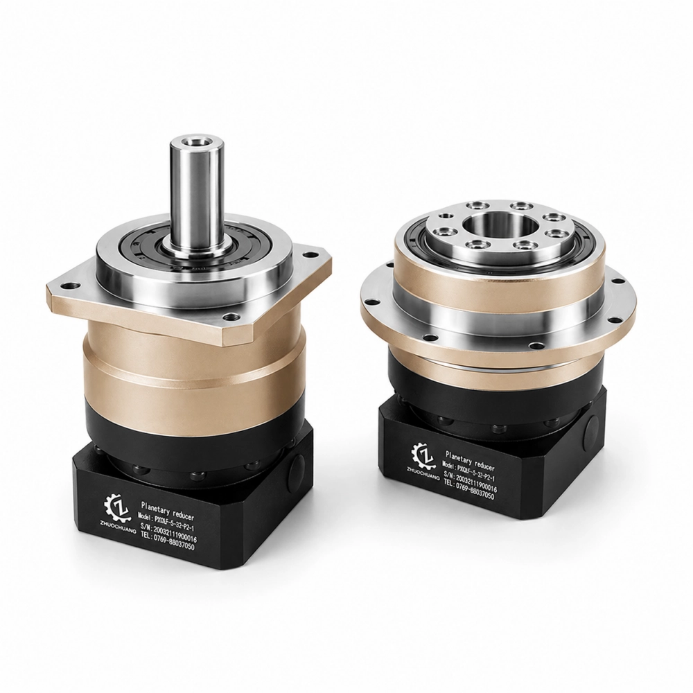
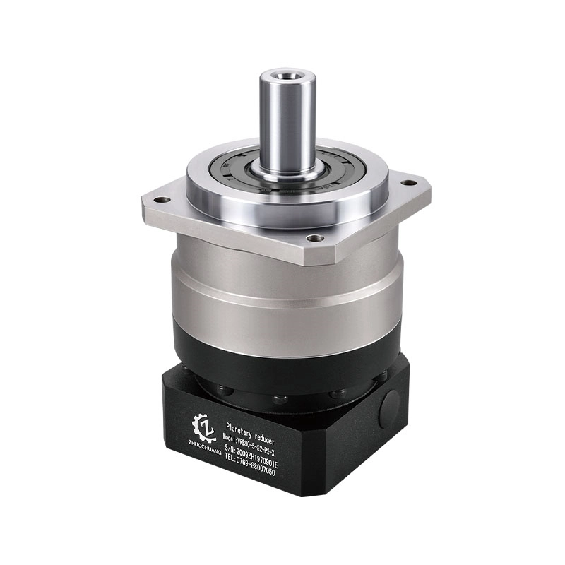
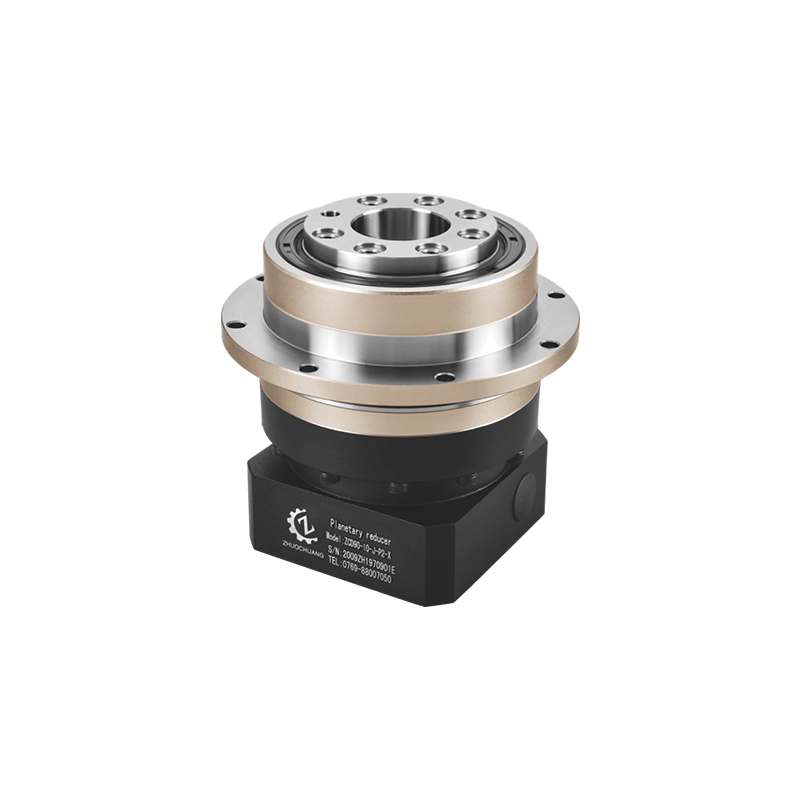
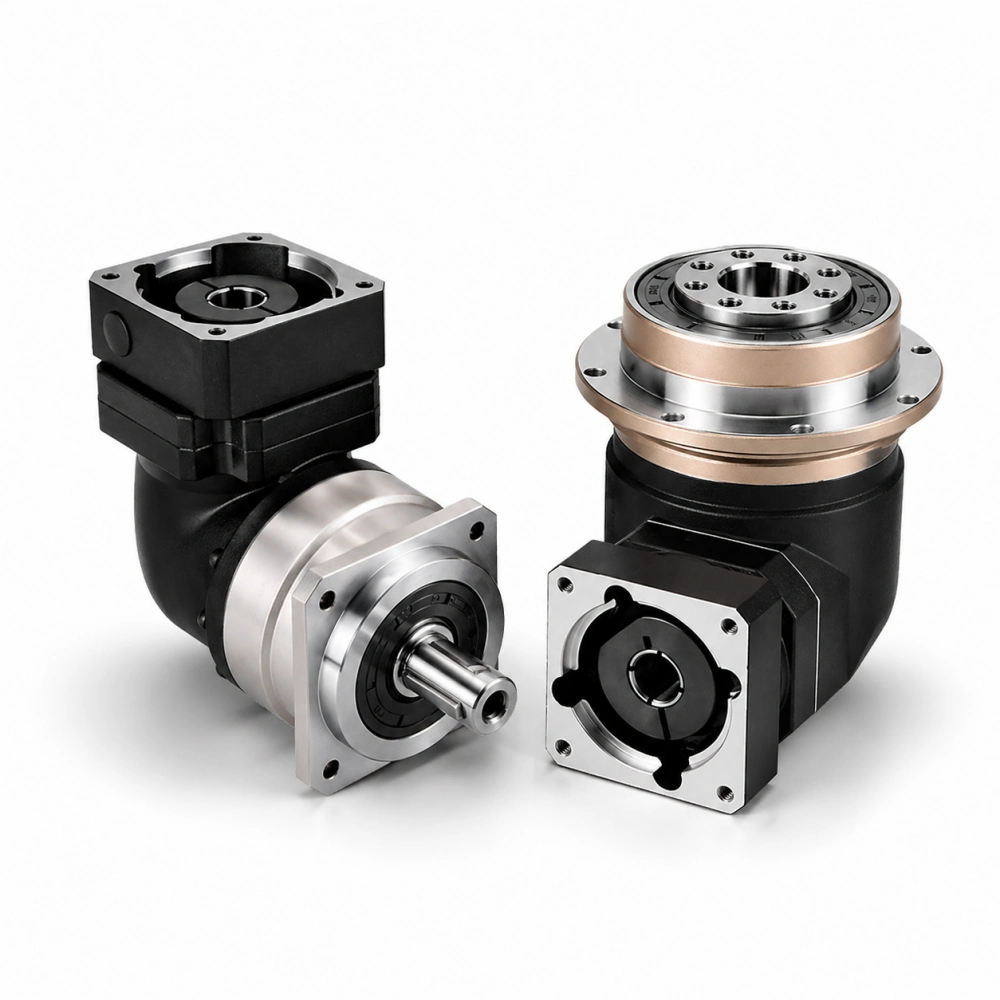
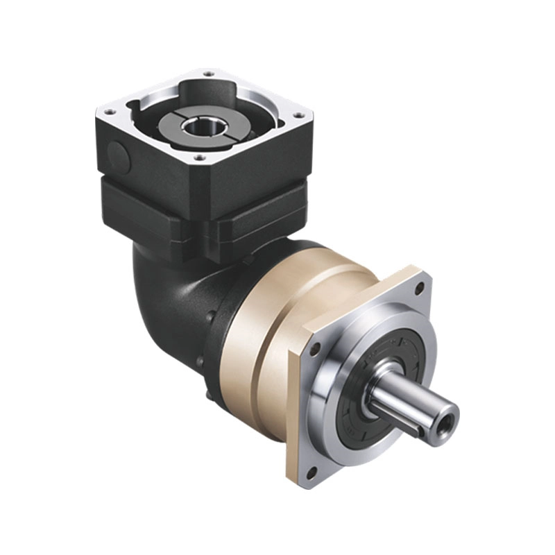
Yes. Planetary gearboxes and hollow rotary tables are our main complete transmission products. Customers may request individual custom gears or discuss a complete motion solution.
Need Custom Spur Gears for Your OEM Project?
Looking for custom spur gears, precision steel gears, metric spur gears or a matched gear and pinion set?
Dongguan Zhuochuang Precision Machinery Co., Ltd. can review your technical drawings, gear specifications and production requirements to assess suitable manufacturing options.
Send us your project details to begin an engineering and quotation review.
What to Include in Your RFQ
- 2D drawing or STEP file
- Spur gear module and tooth count
- Pressure angle and face width
- Bore, hub and mounting dimensions
- Material and heat treatment
- Accuracy and inspection requirements
- Quantity and delivery destination
Dongguan Zhuochuang Precision Machinery Co., Ltd.
ZCJER / PlanetDrivePro
Dalingshan, Dongguan,
Guangdong, China
Email: info@planetdrivepro.com