The Ultimate Guide to Epicyclic Planetary Gear Systems: Mechanics, Math, and Manufacturing
Let’s face it: designing a motion control system is no easy task. When you are trying to squeeze massive torque out of a tiny space while maintaining pinpoint accuracy, standard gearsets simply do not cut it. You need something more robust, more balanced, and incredibly precise. Enter the epicyclic planetary gear system.
At Dongguan Zhuochuang Precision Machinery Co., Ltd (PlanetDrivePro), we specialize in precision planetary gearboxes and epicyclic gear systems for automation, robotics, CNC machinery, and industrial motion control. Whether you are building the next generation of collaborative robots or a heavy-duty CNC machining center, understanding the mechanics behind these gears is your first step toward design success.
In this guide, we are going to strip away the complex jargon. We will explore the kinematic mathematics, explain the gear structure, provide a simple interactive calculator, and look at how epicyclic planetary gear systems are used in real industrial applications.
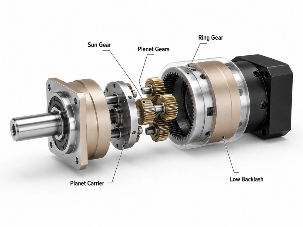
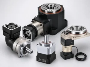
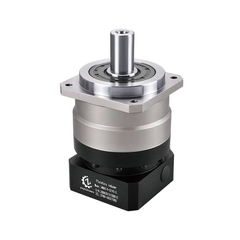
Figure 1: Exploded view of an epicyclic planetary gear system showing the main internal components.
Epicyclic Gear vs Planetary Gear: Is There a Real Difference?
It is one of the most common questions from mechanical engineering students, machine designers, and purchasing teams: What is the difference between an epicyclic gear and a planetary gear?
The simple answer is this: there is no mechanical difference. The two terms describe the same coaxial gear arrangement from different perspectives.
- Epicyclic gearing is the more formal kinematic term. It describes a system where the center of one gear revolves around the center of another gear.
- Planetary gearing is the more common industrial term. Engineers use it because the structure resembles a solar system: a central sun gear, several planet gears, and an outer ring gear.
For practical industrial selection, both terms usually point to the same type of high-torque, compact reduction system. The important question is not which name is used, but whether the ratio, torque, backlash, mounting interface, and motor compatibility fit your machine.
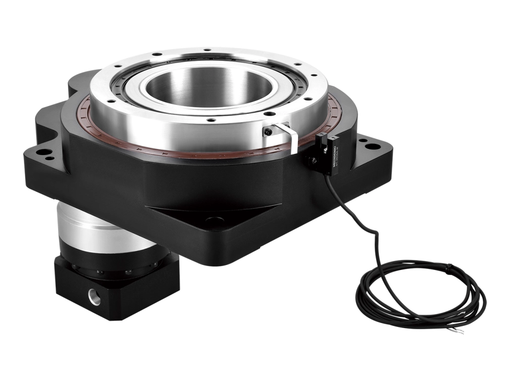
Inside the Mechanism: Components and Load Sharing
If you were to slow down an epicyclic gearbox animation, you would see a synchronized mechanical system where several gears share the transmission load at the same time. This load-sharing structure is the main reason planetary gearboxes can deliver high torque in a compact size.
The system usually contains four main elements:
- The Sun Gear: The central gear, usually driven by the motor input.
- The Planet Gears: The smaller gears surrounding the sun gear. They mesh with both the sun gear and the ring gear.
- The Ring Gear: The outer gear with internal teeth. In many industrial reducers, the ring gear is fixed to the housing.
- The Planet Carrier: The structure that holds the planet gears and delivers the reduced-speed, higher-torque output.
Because multiple planet gears are engaged at the same time, the torque load is distributed across several contact points. This gives the epicyclic planetary gear system a strong advantage in torque density, stiffness, and compact machine design.
One important engineering factor is gear mesh accuracy. If the sun gear, planet gears, and ring gear are not manufactured and assembled precisely, the reducer may generate vibration, uneven wear, noise, and poor motion quality. For servo-driven automation and CNC machinery, precision machining and controlled assembly are essential.
The Epicyclic Gearbox Calculator and Basic Ratio Formula
Engineers often start with the ratio. The reduction ratio determines how motor speed is converted into output speed and how much usable torque is available at the output.
When the ring gear is fixed, which is a common industrial configuration, the basic ratio formula is:
In this equation, Nring is the number of teeth on the ring gear, and Nsun is the number of teeth on the sun gear.
For example, if the sun gear has 15 teeth and the ring gear has 60 teeth, the ratio is:
This means the output speed is reduced by about five times, while output torque is increased, minus efficiency losses.
Lubrication and Thermal Management in High-Speed Applications
A factor often ignored in a simple epicyclic gear simulator is real-world heat. When planetary gears operate at high input speeds, especially with servo motors, friction between the sun gear, planet gears, bearings, and seals generates heat.
If heat is not managed properly, lubricant performance can drop, gear wear can increase, and service life can be reduced.
Effective lubrication is therefore an important part of epicyclic planetary gearbox design. Unlike open gear systems, industrial planetary gearboxes are enclosed. The lubricant must protect the gear teeth, reduce friction, support bearing life, and remain stable during repeated acceleration and deceleration.
At PlanetDrivePro, this is addressed through two practical design considerations:
- High-performance grease: Suitable grease helps maintain a protective film between gear teeth and supports stable operation under repeated load cycles.
- Heat-dissipating housing design: A well-machined housing helps conduct heat away from the gear train and improves long-term reliability.
For high-speed or continuous-duty applications, thermal rating should be checked together with ratio, torque, backlash, and duty cycle.
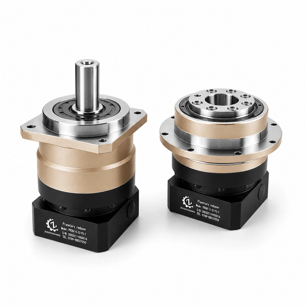
Material and Manufacturing Factors
Theoretical gear ratio is only one part of performance. The reducer also depends on gear material, heat treatment, machining accuracy, bearing support, housing rigidity, and assembly control.
For precision planetary gearboxes, manufacturing quality directly affects backlash, noise, vibration, efficiency, and service life.
- Gear material: High-strength alloy steel is commonly used for load-carrying gears.
- Heat treatment: Proper carburizing and quenching improve surface hardness and wear resistance.
- Gear grinding: Precision grinding helps reduce tooth profile error and improves smooth meshing.
- Controlled assembly: Accurate assembly helps control backlash and maintain repeatability.
For CNC machinery, robotics, and servo positioning systems, these details matter because the reducer is part of the motion control chain. A small mechanical error can become visible as positioning error, vibration, or unstable motion.
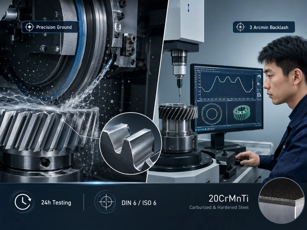
Figure 2: Precision gear grinding helps reduce backlash and improve smooth transmission.
Multi-Stage Epicyclic Gear Trains
A single planetary stage is usually limited by geometry and tooth strength. If a very high ratio is required, the sun gear may become too small if the ratio is forced into one stage.
The common solution is a multi-stage epicyclic gear train.
In a two-stage design, the output of the first planetary stage drives the second stage. The total ratio is the multiplication of the two stage ratios.
For example, a 5:1 first stage combined with a 10:1 second stage creates a total ratio of 50:1.
Multi-stage designs make higher ratios possible, but they also increase length, add components, and may slightly increase efficiency loss and backlash accumulation. That is why ratio selection should be checked together with motor speed, output speed, torque, and machine cycle time.
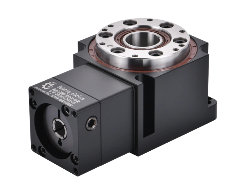
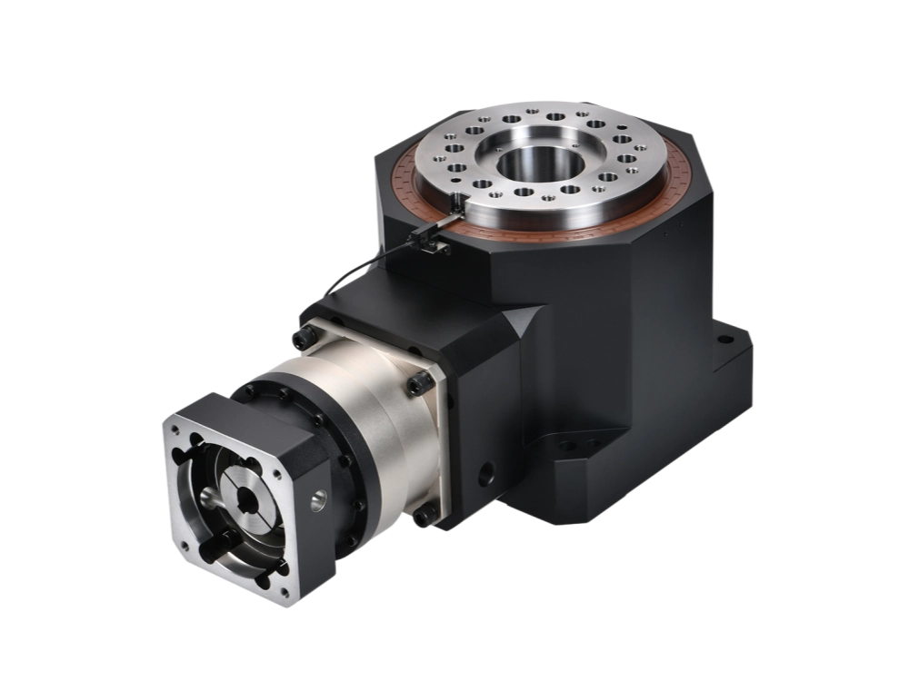
Real-World Applications of Epicyclic Planetary Gear Systems
Epicyclic planetary gear systems are widely used where compact size, high torque density, and controlled motion are required.
You will find them in:
- Industrial robots
- CNC machinery
- Packaging equipment
- Automated guided vehicles
- Rotary positioning systems
- Servo-driven automation modules
- Inspection and assembly equipment
In these machines, the reducer is not only reducing speed. It is helping the motor control the load with the required torque, stiffness, and repeatability.
For related motion-control terminology and complementary transmission resources, you can also visit planetary-drive.com.
Frequently Asked Questions
Is there a difference between epicyclic gear and planetary gear?
No. In most industrial and mechanical contexts, epicyclic gear and planetary gear describe the same gear arrangement. Epicyclic is the formal kinematic term, while planetary is the common industry term.
How does an epicyclic planetary gearbox calculate ratio?
For a common fixed-ring arrangement, the ratio is calculated as R = 1 + Nring / Nsun. The exact formula may change if a different member is fixed or used as input/output.
Why are planetary gearboxes compact but strong?
Planetary gearboxes use multiple planet gears to share the load. This allows high torque transmission in a smaller housing compared with many simple gear arrangements.
Do you offer custom ratios for OEM projects?
Yes. Standard ratios such as 3:1, 5:1, and 10:1 fit many applications, but custom configurations may be reviewed for OEM projects depending on ratio, torque, size, and quantity requirements.
Where are epicyclic planetary gear systems commonly used?
They are commonly used in robotics, CNC machinery, packaging equipment, automated guided vehicles, precision positioning systems, and servo-driven automation equipment.
Need Help Selecting a Precision Planetary Gearbox?
Understanding the epicyclic planetary gear system helps engineers choose the correct ratio, torque capacity, backlash grade, and mounting configuration for real industrial equipment.
Dongguan Zhuochuang Precision Machinery Co., Ltd manufactures precision planetary gearboxes for automation, CNC machinery, robotics, packaging equipment, and servo-driven motion systems.
Request a Custom Quote