
Selecting a servo gear reducer is straightforward in principle and surprisingly easy to get wrong in practice. The ratio is calculable. The torque is measurable. The backlash grade is specifiable. And yet drive systems end up mismatched — undersized for peak loads, over-specified for the positioning tolerance, or mechanically incompatible with the motor — because the selection was made from a datasheet rather than from a structured set of requirements.
This guide is a selection framework for engineers and procurement teams specifying servo gear reducers for automation equipment. It covers what information you need before talking to a supplier, what the specification parameters actually mean in a production environment, what to confirm before placing an order, and what distinguishes a precision servo gear reducer from a standard industrial unit.
What Is a Servo Gear Reducer — and What Sets It Apart
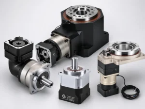
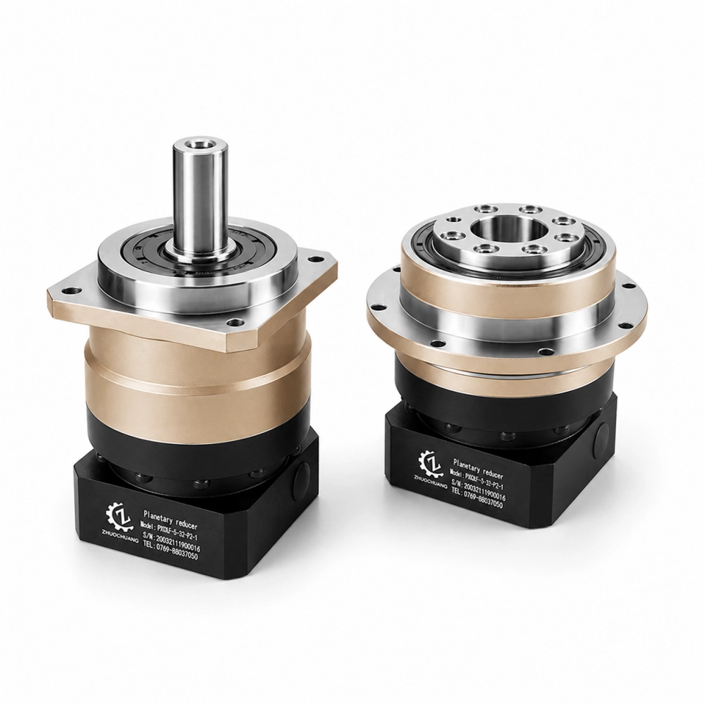
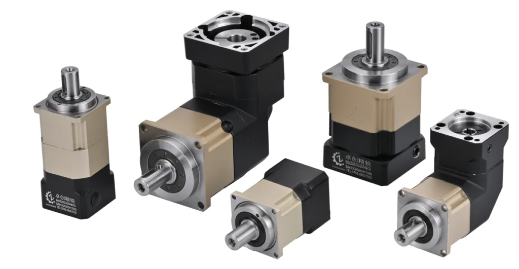
A servo reducer — sometimes called a servo speed reducer, servo gear reducer, or servo motor gear reducer — is a precision-built mechanical reducer designed to operate as part of a closed-loop servo drive system. The term covers the same product category as servo gearbox or servo planetary gearbox; the terminology varies by region and industry but the product is the same.
What separates a servo reducer from a standard industrial reducer is not a single feature but a combination of design priorities:
Backlash is measured, not assumed. A standard industrial reducer may carry a nominal backlash specification from the design. A servo reducer at precision grade is individually tested and shipped with measured backlash data. The difference matters because manufacturing variation means nominal backlash and actual backlash can diverge — and in a position-controlled servo loop, actual backlash is what determines system performance.
Torsional stiffness is specified. Servo control loops are sensitive to compliance in the mechanical chain. A reducer that winds up under load before transmitting motion introduces phase lag that the controller has to fight. Precision servo reducers publish torsional stiffness in Nm/arcmin. Standard industrial reducers typically do not.
Input inertia is documented. The reducer’s own rotor inertia contributes to the total reflected inertia the servo motor must accelerate. For correct servo sizing, this figure needs to be known and included in the inertia calculation. A supplier who can provide the input-side inertia of their reducer is a supplier who understands servo applications.
Motor interface is precise. Servo motors have standardised flange dimensions and shaft tolerances. A precision servo reducer provides input adapter plates machined to match specific motor flange standards — not generic hole patterns that require shimming or improvised connections.
The Six Parameters That Define a Servo Gear Reducer Specification
Before contacting a servo gear reducer supplier, these six parameters should be defined from the application requirements. They determine which products are candidates and which are not.
1. Gear Ratio
The ratio is determined by the required output speed relative to the motor’s rated speed. Define the required output speed at full load — the speed the load actually moves at during the application’s duty cycle — and divide the motor’s rated speed by it.
A servo motor rated at 3,000 RPM driving an output that needs to move at 60 RPM requires a 50:1 ratio. Single-stage planetary reducers typically cover 3:1 to 10:1; two-stage units cover up to approximately 100:1; three-stage units go higher. If your ratio falls outside a standard stage combination, confirm with the supplier whether a non-standard ratio is available and at what lead time.
2. Output Torque — Rated and Peak
Two torque figures matter: the rated continuous torque (what the reducer transmits during normal operation) and the peak torque (the maximum momentary torque during acceleration, deceleration, or emergency stops).
Rated output torque = motor rated torque × ratio × efficiency
Apply a service factor based on application conditions — typically 1.2 to 1.5 for standard automation, higher for shock-loaded or high-cycle applications. The reducer’s rated continuous torque specification must exceed this figure.
Peak torque is usually 2–3× the continuous rated torque for servo motors. The reducer’s maximum momentary torque specification must accommodate the peak without tooth damage. Confirm both figures — running a reducer at rated continuous torque is not the same as running it at peak torque intermittently, and a unit rated for one may not be rated for the other.
3. Backlash Grade
The required backlash grade follows from the application’s positioning accuracy requirement. Working backwards from the output tolerance:
- General automation, transfer systems: ≤15 arcmin is typically adequate
- CNC auxiliary axes, indexing tables: ≤8 arcmin
- Precision servo positioning, assembly equipment: ≤3 arcmin
- Robotic joints, contouring axes: ≤1 arcmin
Specify the backlash requirement from the application tolerance, not from a preference for the highest grade. Over-specifying adds cost without improving performance when the positioning tolerance doesn’t require it. Under-specifying produces a system that can’t hold its programmed path.
4. Mounting Configuration and Output Interface
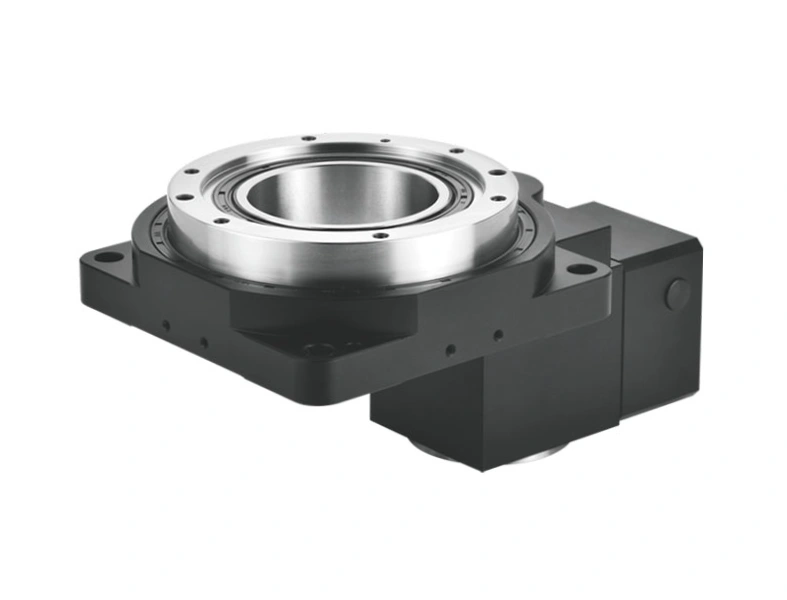
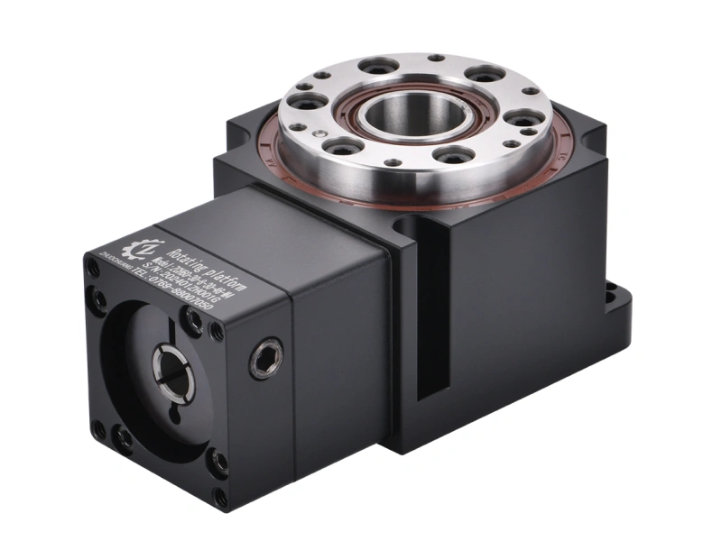
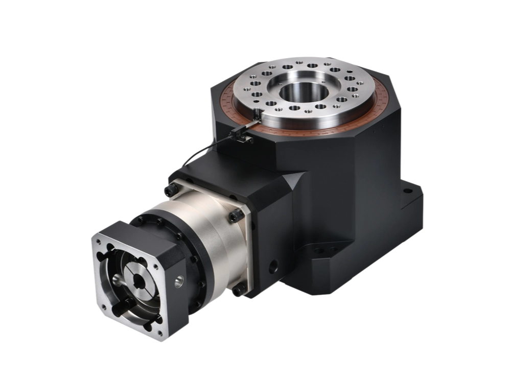
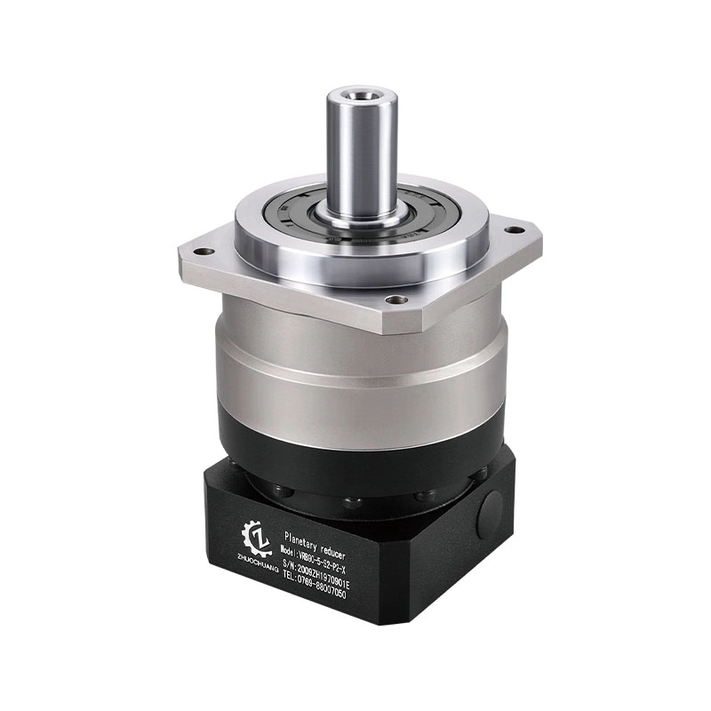
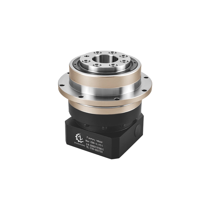
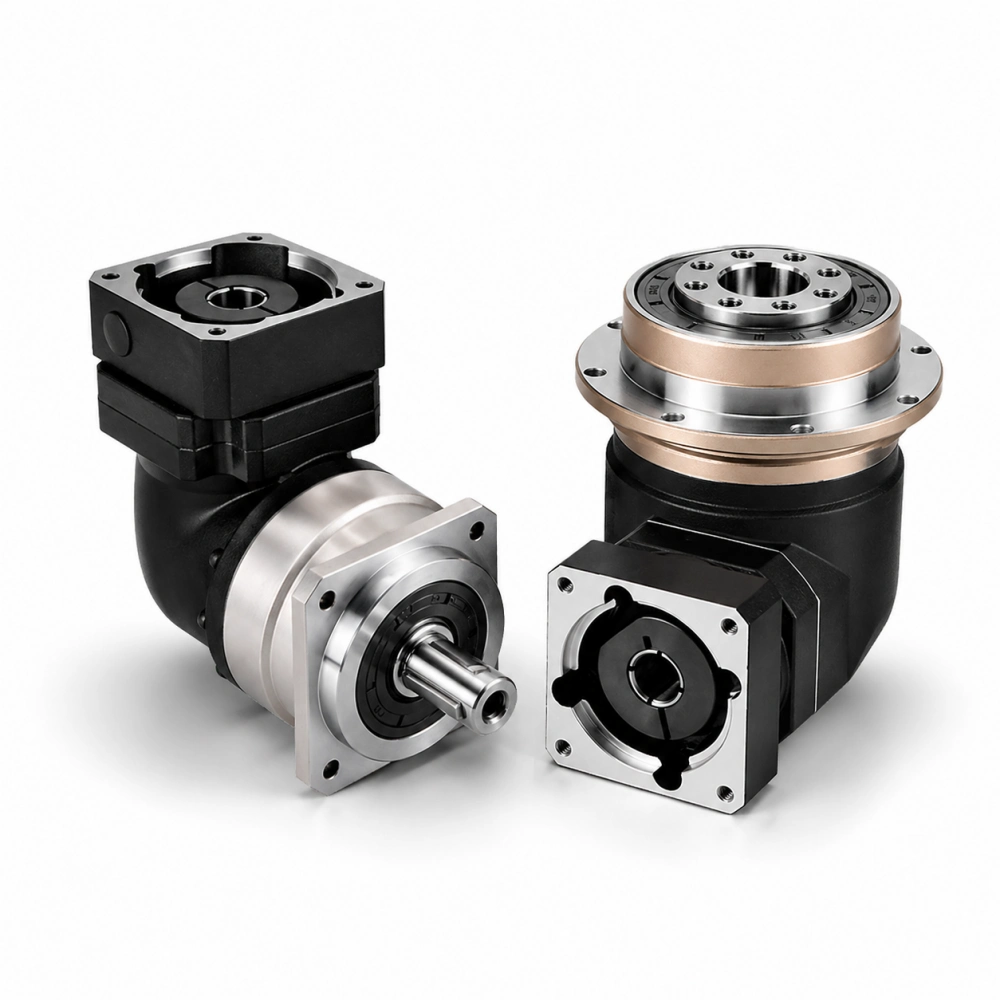
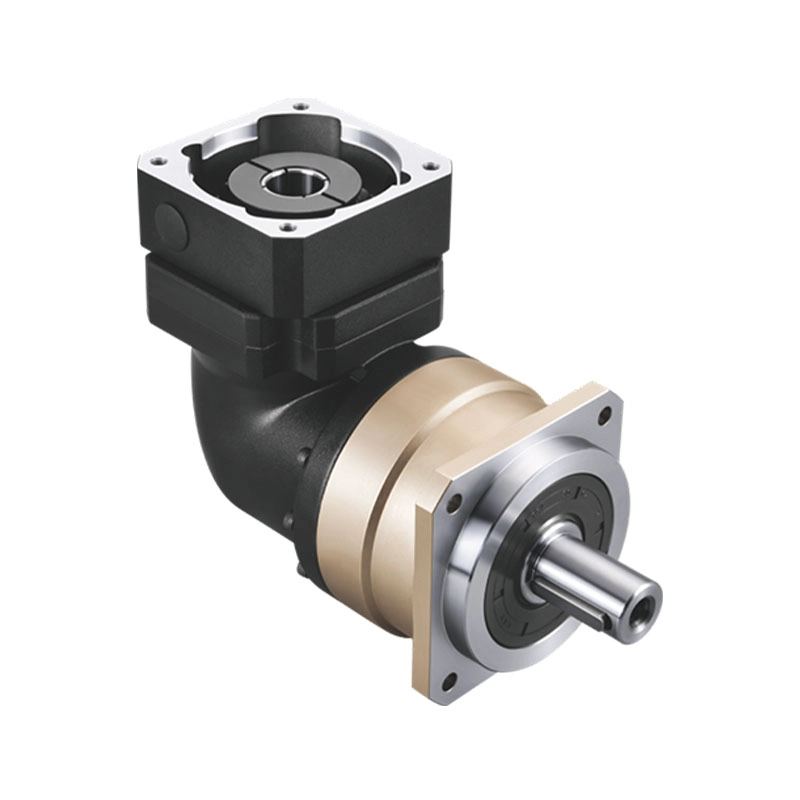
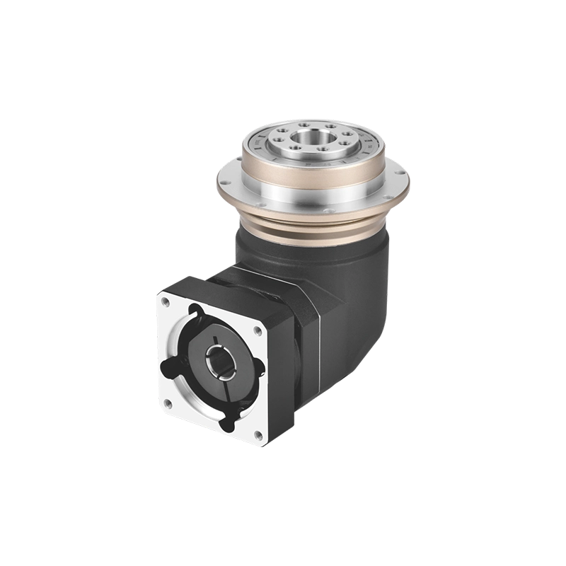
The mounting configuration — inline (coaxial) or right-angle — is a layout decision driven by the machine’s physical constraints, not a performance decision. Inline is the default for most servo automation; right-angle is used when the motor and load axes must be perpendicular.
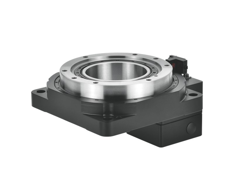
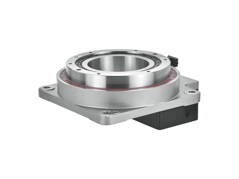
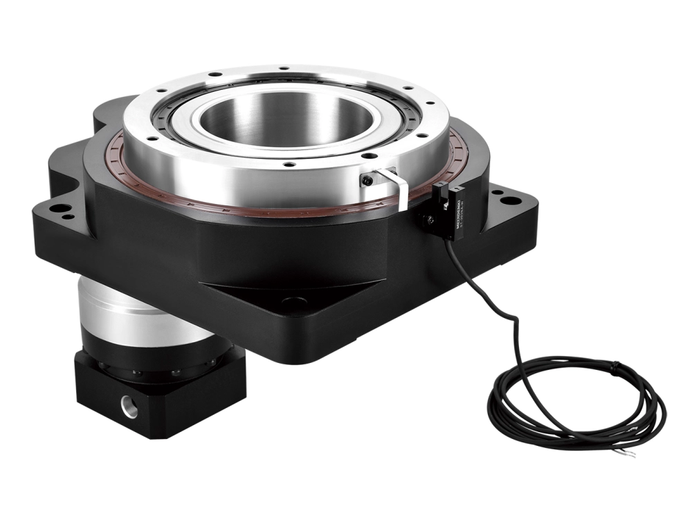
The output interface must match the mechanical connection point on the machine: smooth shaft, keyed shaft, flanged output, or hollow bore. Confirm output shaft diameter, key dimensions if applicable, and the flange bolt pattern. These are not adjustable after the order is placed.
5. Input Interface — Motor Compatibility
The input adapter must match your servo motor’s flange standard and shaft dimensions exactly. Common standards include IEC metric flange sizes (80mm, 100mm, 130mm, 180mm, 230mm) and NEMA frame sizes for North American motor families. Confirm the specific flange standard, pilot bore diameter, and shaft connection method — clamping hub, key, or shrink disc — for your motor model.
Misalignment at the motor connection adds to the effective backlash at the system level and introduces radial loads on the motor bearing that it was not designed to carry. This is a detail that shows up in service life, not always at commissioning.
6. Duty Cycle and Thermal Rating
Every servo gear reducer has a thermal power rating — a maximum sustained input power that keeps the housing within its operating temperature limits. Exceeding this in continuous-duty applications doesn’t cause immediate failure; it degrades lubricant faster, shortens bearing life, and eventually accelerates wear throughout the gear train.
Continuous input power = motor continuous torque × rated angular velocity (rad/s)
Compare this against the reducer’s thermal rating at your ambient temperature. At elevated ambient temperatures — above the reference temperature in the datasheet, often 20–25°C — the thermal rating decreases because there’s less temperature differential to drive heat dissipation. Request the thermal derating curve for applications in warm or poorly ventilated environments.
Precision Servo Gear Reducers vs Standard Grades — What the Difference Costs
Precision servo gear reducers carry a cost premium over standard industrial grades. Understanding what that premium buys — and whether your application needs it — avoids both over-spending and under-specifying.
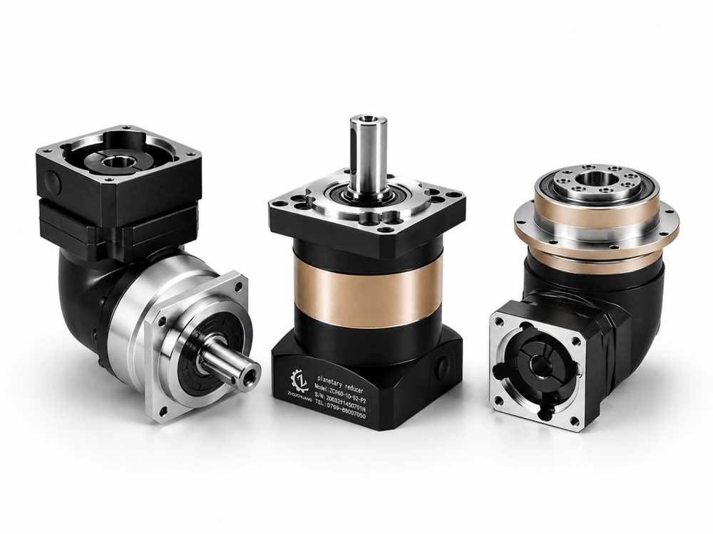
The precision premium comes from three manufacturing differences:
Ground gear teeth. Hobbed or shaved gear teeth are adequate for standard industrial applications. Ground teeth have surface roughness values 5–10× lower, which produces tighter backlash, lower friction at the mesh, and marginally better efficiency. For backlash specifications below approximately 5 arcminutes, ground teeth are required — the manufacturing tolerances achievable with hobbing cannot consistently produce lower backlash.
Controlled bearing preload. Precision servo reducers use pre-selected bearings assembled with controlled preload to eliminate radial and axial play in the carrier assembly. This contributes directly to the backlash specification and to the torsional stiffness. It’s a manufacturing process step, not a component choice — it requires measurement during assembly and adds production time.
Individual unit testing. Standard grades are typically sample-tested; precision grades are individually tested. The cost difference reflects the test time per unit, not just the manufacturing process.
For applications with backlash requirements of 8 arcminutes or less, precision servo grade is the practical choice. For applications with wider tolerances, standard grade is often adequate at lower cost.
Extremely Rugged Servo Reducers — When the Environment Demands More
Most precision servo gear reducers are designed for clean industrial environments — inside machine enclosures, in temperature-controlled cells, away from direct contamination. Some applications demand more: outdoor installations, foundry and metalworking environments with abrasive dust, food processing with chemical wash-down, and mobile machinery where shock and vibration loads are continuous.
Extremely rugged servo reducers — sometimes described as heavy-duty servo reducers, protected servo reducers, or IP67/IP69K-rated servo reducers — address these environments through housing material and seal specification, not through different gear geometry. The mechanical design is similar to standard servo reducers; the differences are:
- Higher IP rating (IP67 or IP69K) for wash-down and dust exclusion
- Stainless steel or hard-anodised housing for corrosion resistance
- Reinforced seals at input and output shafts
- Extended temperature range lubricant specification
For applications in clean industrial environments, the standard housing is adequate. For food, pharmaceutical, outdoor, or high-contamination installations, confirm the IP rating and housing material before ordering — retrofitting a standard-grade reducer into a wet environment that wasn’t specified for it produces a short service life.
Servo Worm Reducer — When It’s the Right Choice and When It Isn’t
The servo worm reducer — a worm gear reducer paired with a servo motor — appears in servo applications where the right-angle output and high single-stage ratio are attractive, typically in vertical load positioning where the self-locking characteristic provides a failsafe hold without a separate brake.
For most precision servo positioning applications, a worm reducer is not the correct choice. Worm gear efficiency typically runs 70–90%, which means significant heat generation at servo power levels in continuous duty. The sliding-contact tooth mesh produces higher static friction than rolling-contact planetary gears, making precise low-speed positioning less consistent. Backlash is typically higher at equivalent cost compared to planetary alternatives.
The cases where a servo worm reducer is legitimately appropriate:
- Low-duty-cycle applications where continuous thermal load is not a constraint
- Vertical load holding without separate brake
- Very high ratio requirements (above 100:1) in a single stage where two-stage planetary adds unwanted length
- Applications where the approximate cost advantage of worm gear construction outweighs the efficiency and precision limitations
For everything else — continuous duty servo positioning, contouring axes, robotic joints, high-cycle automation — the servo planetary gear reducer is the correct tool. The efficiency, backlash, and stiffness performance of the planetary arrangement is consistently better for these applications at comparable or lower cost per Nm of output torque.
What to Ask a Servo Gear Reducer Supplier
A supplier meeting or RFQ for servo motor gear reducers should produce answers to these questions before a purchase order is issued:
Specification confirmation:
- Is the published backlash measured on each unit, or is it a design specification?
- Is unit-level backlash data available with the shipment?
- Are gear teeth ground or hobbed for this grade?
- What is the torsional stiffness at rated torque?
Motor compatibility:
- Is a motor adapter available for my specific motor model and flange standard?
- What is the input shaft connection method and clamping hub bore tolerance?
Thermal and duty cycle:
- What is the thermal power rating at my ambient temperature?
- Is a thermal derating curve available?
Lead time and supply:
- Is my required ratio in the standard range, or is it a custom?
- What is the lead time for standard vs. custom ratios?
- Is volume pricing available, and at what quantity break?
Documentation:
- Is a mounting and installation guide available?
- What is the relubrication interval and specified lubricant?
- Is a warranty period stated, and what does it cover?
A supplier who answers these questions clearly — with data rather than assurances — is a supplier with a manufacturable product and a real quality system behind it. Suppliers who deflect specific questions about their manufacturing process or testing method are suppliers worth approaching with caution.
Closing
A servo gear reducer selection done correctly is a one-time investment of engineering time that pays back across the service life of the machine. Done incorrectly, it produces commissioning problems, performance shortfalls, and early replacement cycles that cost far more than the original specification effort.
The framework is consistent regardless of application: define the six parameters from the load requirements, specify the backlash grade from the positioning accuracy tolerance, confirm the motor interface from the specific motor model, and verify thermal and duty-cycle ratings before placing the order. Then ask the supplier the right questions and evaluate the answers critically.
At Zhuochuang, we manufacture precision servo planetary gear reducers designed for industrial automation, robotics, CNC machinery, and packaging equipment. Our units are available in inline and right-angle configurations, with ground gear teeth for precision grades, individual backlash testing, and motor adapters for common servo motor brands. If you’re working through a specification and want confirmation that the right unit exists for your application before committing to an order, our technical team is ready to help.
Browse our servo gear reducer range → Contact us for specification support and quotation →
Dongguan Zhuochuang Precision Machinery Co., Ltd planetdrivepro.com
Related reading:
A clear and practical guide to selecting a servo gear reducer. The explanations of torque, speed, backlash, and motor compatibility are easy to understand.
The selection checklist is especially useful for engineers comparing different options for automation projects. Thanks for sharing this helpful information.