
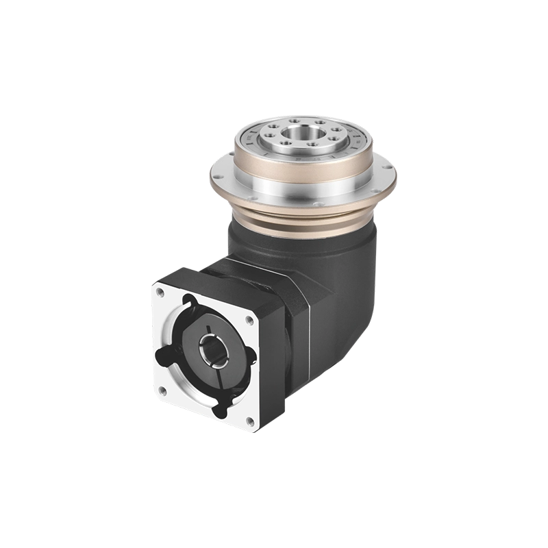
Replacement engineering guide
A failed or discontinued reducer creates an urgent purchasing problem, but urgency is exactly when a visually similar gearbox becomes expensive. The replacement may have the same nominal ratio and still move the motor, shaft, mounting face or driven component far enough to require a new bracket, coupling or machine program.
A reliable right angle gearbox replacement therefore begins with the machine interface—not with a catalog photo. The old nameplate is useful evidence, but the approved substitute must also reproduce the required motion, fit the available envelope and survive the real duty cycle. This guide shows what to measure, what can change safely and what must be confirmed before a purchase order is released.
Need a Replacement Without Redesigning the Machine?
Send the old model number, motor model, gearbox photos and a marked installation drawing. We can check the missing dimensions and identify whether a standard VRBR or ZCDR configuration is a practical starting point.
Send Your Replacement Details →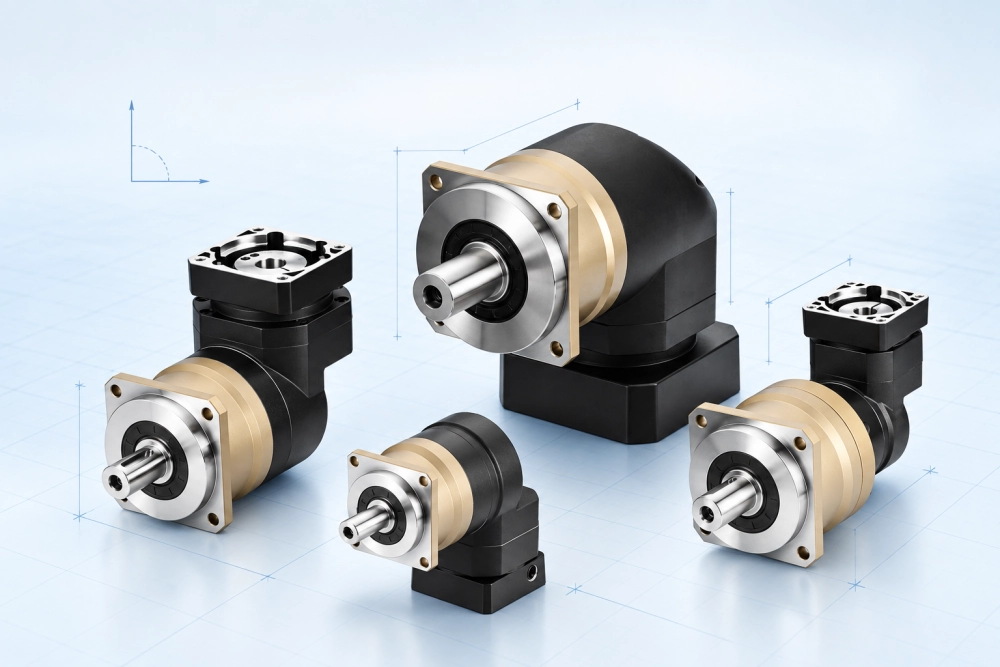
Start the Right Angle Gearbox Replacement with a Match Sheet
Create one page that records “existing unit” and “proposed unit” side by side. This prevents scattered information from being lost across emails. It also separates facts measured on the machine from assumptions copied from an old catalog.
Do not write “same size” in the match sheet. Record millimeters and tolerances. Do not write “same torque.” Record the torque value, duration and repetition. A useful right angle gearbox replacement decision is made from comparable data, not similar adjectives.
Four Gearbox Replacement Dimensions That Stop a Retrofit
The most important gearbox replacement dimensions are not always the largest overall dimensions. A 2 mm error at the locating pilot may stop assembly, while 20 mm of unused clearance behind the motor may not matter at all. Check these four interfaces in order.
1. Motor-Side Locating and Shaft Engagement
The adapter must match the motor pilot, bolt circle, shaft diameter and usable shaft length. Confirm whether the motor shaft has a key, a smooth clamping surface or another connection. The coupling must engage correctly without bottoming out or leaving inadequate contact length. A plate that can be bolted on is not automatically a correctly aligned adapter.
2. Gearbox Mounting Face and Center Height
Mark the machine datum used by the current reducer. Measure the mounting face, pilot, bolt pattern and the output centerline relative to that datum. If the new housing changes center height, the driven pulley, screw, rack or coupling may no longer align even when the gearbox fits inside the guard.
3. Output Shaft or Output Flange
For a shaft output, record diameter, usable length, shoulder position, keyway width and keyway location. For a flange output, record pilot diameter, hole count, pitch circle, thread and mounting-face offset. These gearbox replacement dimensions determine whether the existing driven component can be reused.
4. Motor and Cable Clearance
A right-angle arrangement is often chosen because the machine is short in the axial direction. Check the complete motor envelope, connector orientation, cable bend radius, access for tools and space needed to remove the motor later. A replacement that fits only before the surrounding panels are installed is not serviceable.
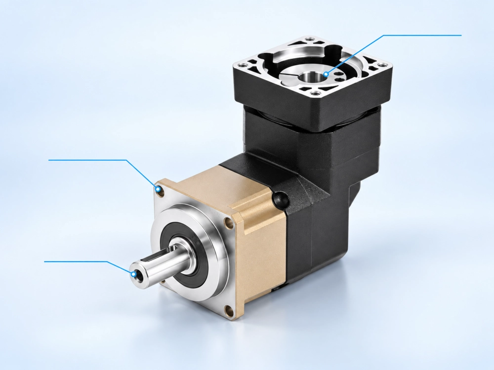
Servo Gearbox Replacement: Match the Motion, Not Only the Ratio
A servo gearbox replacement can rotate correctly during a no-load test and still perform poorly on the machine. Ratio establishes the relationship between motor and output speed, but it does not describe backlash, torsional stiffness, inertia, efficiency or permitted peak events.
| Check | Why it matters in a servo retrofit | Evidence to request |
|---|---|---|
| Actual ratio | Changes output speed, available torque and machine timing. | Exact catalog ratio and model code—not only the requested nominal ratio. |
| Total output backlash | Affects reversal error, registration and positioning repeatability. | Specified backlash grade and the supplier’s measurement condition. |
| Torsional stiffness | Influences settling time and how directly motor commands reach the load. | Model-specific value or an engineering confirmation for the duty. |
| Input and gearbox inertia | Changes servo tuning and acceleration response. | Inertia data for the selected size, ratio and stage count. |
| Rated and emergency torque | Separates continuous thermal duty from short acceleration or stop events. | Allowed torque values, duration, frequency and service assumptions. |
For a frequently reversing axis, ask whether the published backlash applies to the complete right-angle assembly. A value for only one internal stage does not describe total output behavior. For a high-cycle axis, provide the full speed-and-torque cycle rather than a single average number.
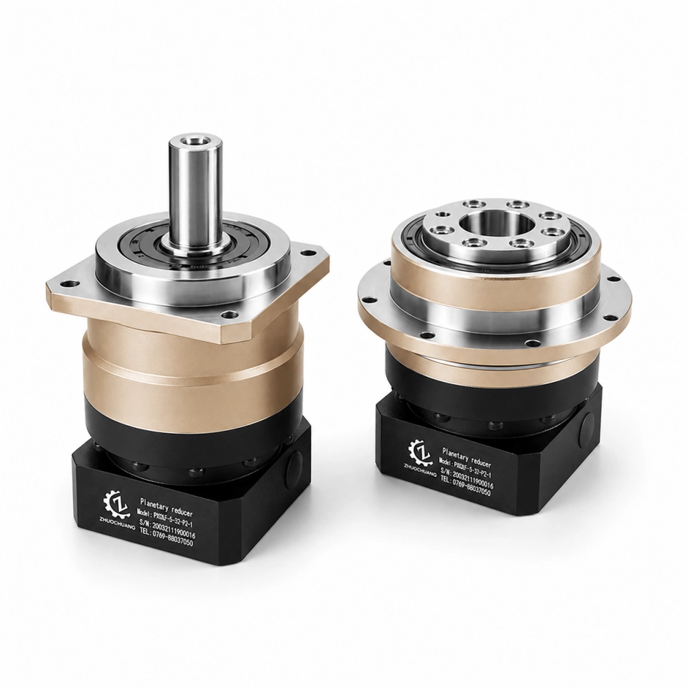
When a Replacement Planetary Gearbox Is Not Drop-In
The phrase replacement planetary gearbox is often interpreted as “same function, same installation.” Those are different claims. Three outcomes are possible, and the purchase documents should state which one has been accepted.
| Replacement level | What remains unchanged | What the project must allow |
|---|---|---|
| Direct mechanical replacement | Critical mounting, input and output interfaces; ratio and rotation behavior. | Only normal assembly and servo verification. |
| Adapter-assisted replacement | Machine datum and driven component. | A documented motor adapter, spacer, coupling or mounting plate. |
| Functional replacement | Required output motion and load capability. | Mechanical redesign, program changes or a new driven connection. |
A proposed replacement planetary gearbox should never be called “drop-in” merely because its flange is similar. Put the new outline drawing over the old drawing using the same datum. Highlight every deviation. This simple overlay makes hidden conflicts visible before metal is cut.
Have an Old Drawing but No Usable Model Code?
Send the drawing plus clear photos of the nameplate, motor flange, mounting face and output connection. Include the machine function and quantity. We will tell you which measurements are still needed for a responsible review.
Email the Drawing Package →Loads That a Right Angle Gearbox Replacement Must Carry
Output torque is only the twisting load. A pulley, sprocket, pinion or offset arm also creates radial force and an overturning moment at the output bearing. Helical gearing, an inclined mechanism or process force may add axial load. The distance from the gearbox face to the point of force application is essential because the same force creates a larger moment as that distance increases.
Record the driven component, its pitch diameter, belt or chain tension, load direction and overhung distance. If the original unit failed at the output bearing or seal, do not assume that matching its frame size will cure the problem. The mounting arrangement or applied moment may need to change.
A sound right angle gearbox replacement review distinguishes the load carried by the gearbox from the load carried by external machine bearings. If an external support can remove a severe overhung load, that may be a better engineering solution than simply choosing a larger reducer.
Approve the Servo Gearbox Replacement in Two Gates
Gate A: Can It Physically Enter and Connect?
- Motor flange, shaft and coupling are confirmed.
- Mounting pilot, bolt pattern and output centerline match the machine datum.
- Output shaft or flange connects to the existing driven component.
- Motor, connector, cable and service-tool clearances are available.
- Approved mounting orientation is shown on the drawing.
Gate B: Can It Run the Real Cycle?
- Exact ratio and output direction are confirmed.
- Continuous, acceleration, deceleration and emergency-stop torque are separated.
- Backlash and stiffness fit the machine’s accuracy and settling-time requirement.
- Radial, axial and moment loads are checked at their actual application positions.
- Input speed, starts per hour, operating time, temperature and contamination are declared.
This two-gate method keeps a convenient mechanical fit from hiding a performance problem. It also prevents an excellent precision reducer from being selected when it cannot be installed or maintained in the available space. Keep the signed checklist with the right angle gearbox replacement drawing revision.
Commission the Right Angle Gearbox Replacement Before Production
Installation is the final part of the replacement decision. Clean the motor shaft and mating faces, remove protective oil where the coupling must grip, and check that no burr or paint prevents the locating pilot from seating. Turn the gearbox input only as required by the manufacturer to place the clamping screw in an accessible position. Never pull a misaligned motor into place with the mounting bolts.
The motor shaft should enter the input connection smoothly and the two flange faces should meet without a visible gap. Tighten the input clamp and motor fasteners with the specified sequence and torque for the selected model; a universal tightening value should not be assumed. Reinstall any sealing plug or inspection cover that was removed during assembly.
Before releasing the machine, rotate the assembly by hand where safe, then run it unloaded at low speed. Confirm output direction, abnormal sound, vibration and leakage. Increase speed and load in controlled steps while observing temperature and servo behavior. For a precision servo gearbox replacement, record the initial backlash or positioning result so later maintenance has a commissioning baseline.
Build an RFQ That Produces a Usable Replacement Proposal
A short but complete RFQ is more valuable than a long email chain. For a replacement planetary gearbox, send the information below in one package:
- Old manufacturer and full model code, including every suffix.
- Photos of the full assembly, nameplate, motor interface, mounting face and output.
- Old outline drawing and your marked critical dimensions.
- Servo motor manufacturer and complete model number.
- Required ratio, output speed and direction of rotation.
- Continuous torque, peak torque, event duration and cycles per hour.
- Backlash or machine positioning requirement.
- Radial and axial forces, overhung distance and driven-component details.
- Daily operating time, ambient conditions and required quantity.
- Whether direct interchangeability is mandatory or an adapter/redesign is acceptable.
When some data is unavailable, label it “unknown” rather than guessing. Photos with a scale and a simple hand sketch can resolve many early questions, but final approval should use a controlled drawing. This approach gives a manufacturer enough evidence to distinguish a standard model from a genuine custom requirement.
VRBR or ZCDR as a Right Angle Gearbox Replacement Starting Point
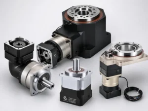
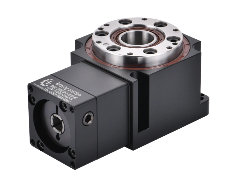
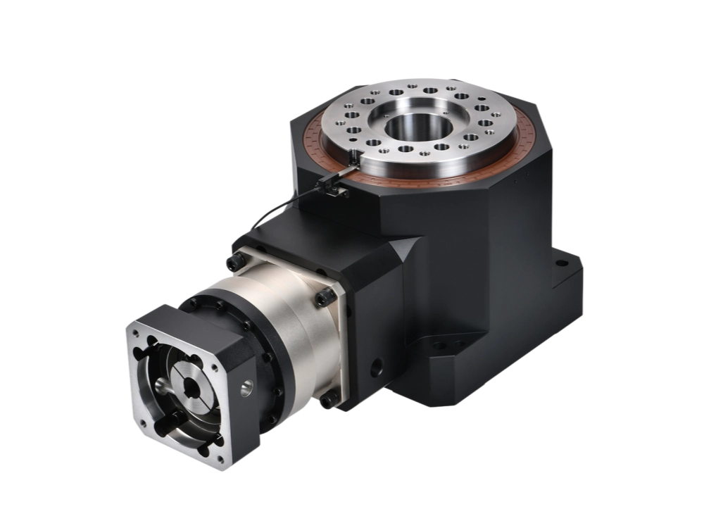
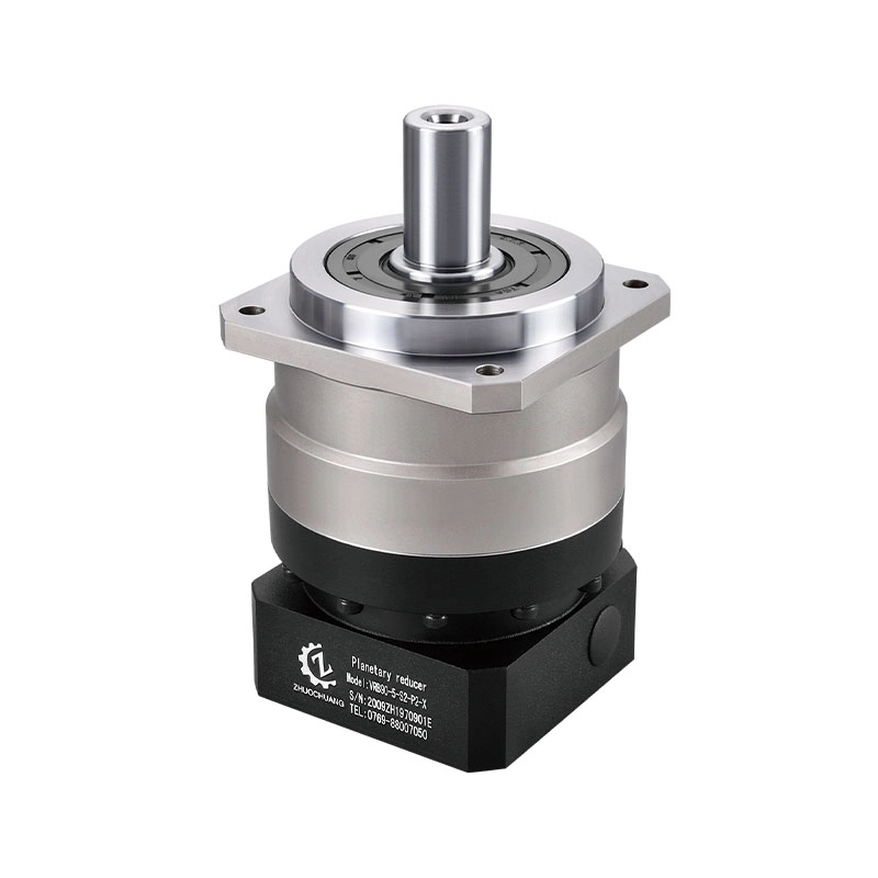
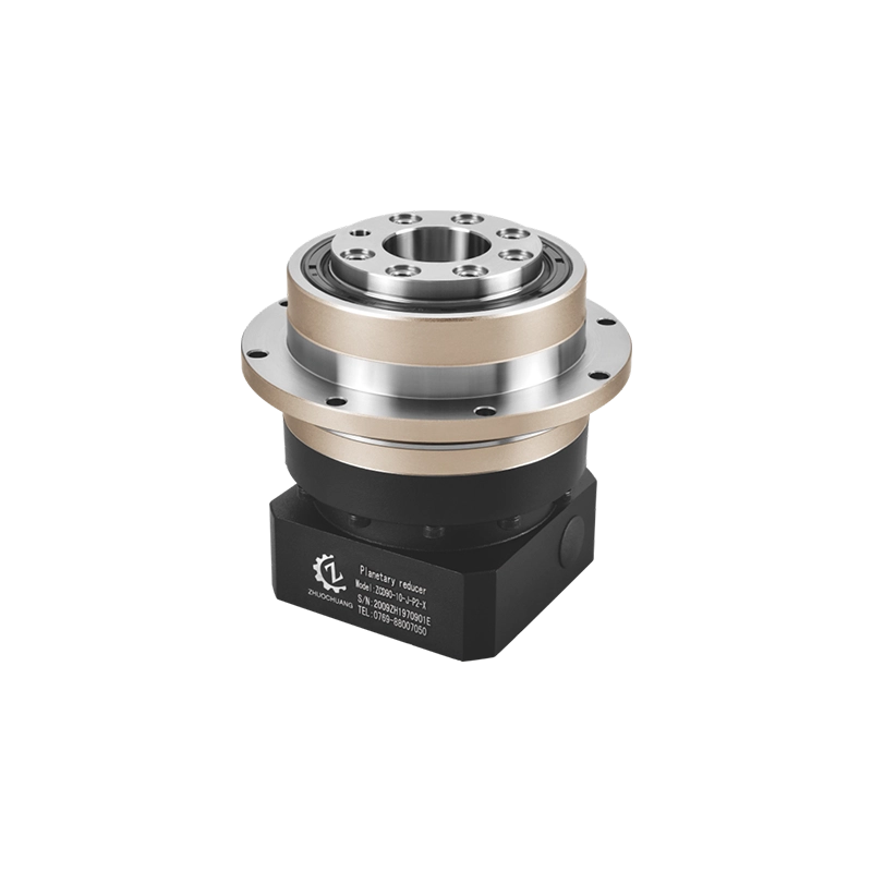
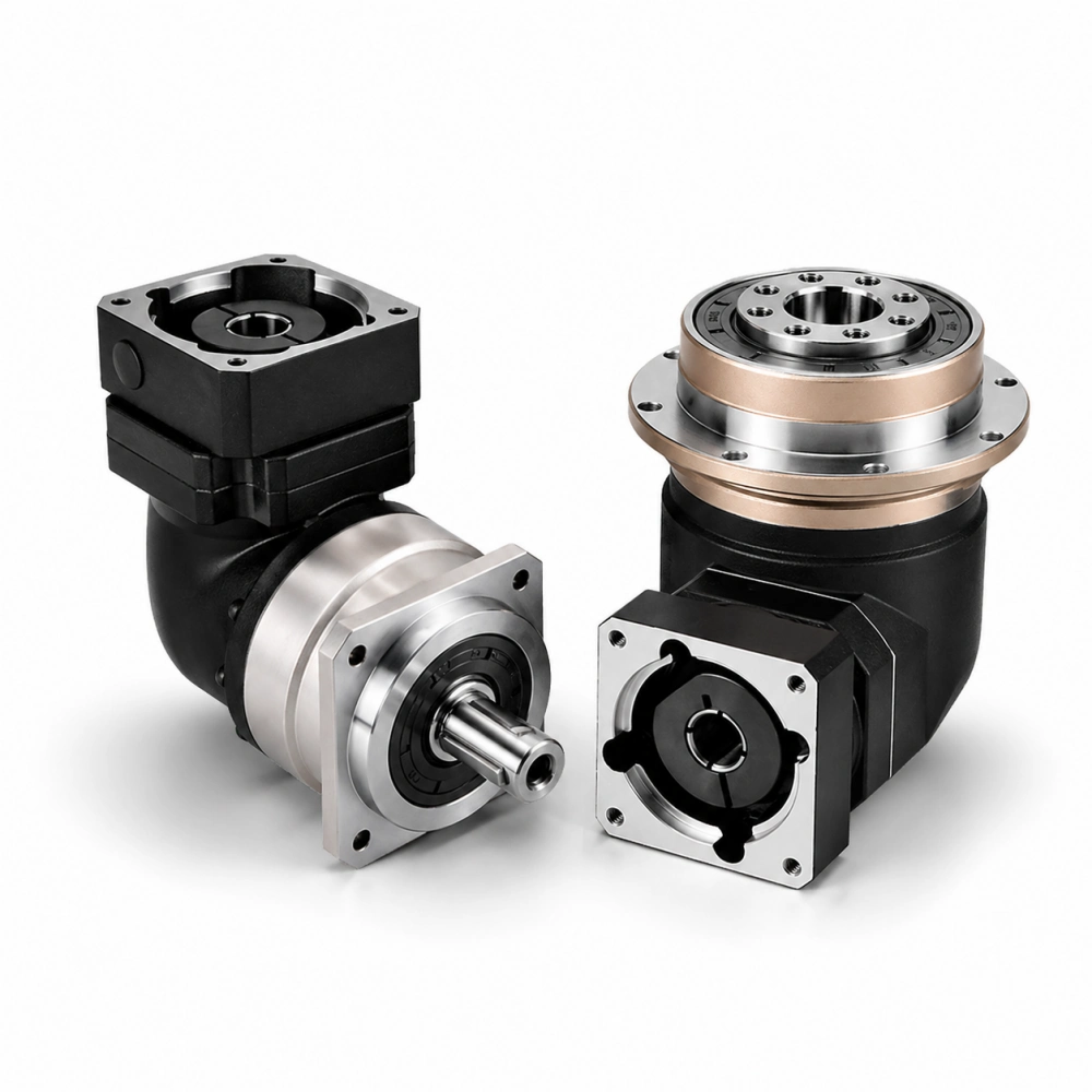
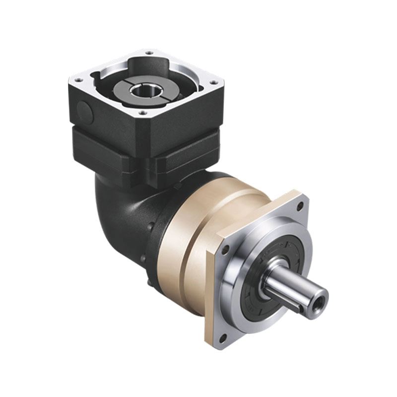
Zhuochuang’s VRBR Series provides a shaft-output right-angle planetary format for compact servo-driven layouts. The right-angle planetary gearbox range also includes ZCDR configurations where a different output and machine interface may be required.
These series names are starting points, not automatic substitutes. Final selection still depends on the complete motor interface, ratio, gearbox replacement dimensions, load cycle, output connection and installation drawing. For background on why a general-purpose 90-degree drive is not always equivalent to a precision servo reducer, read the existing 90 degree gear reducer guide.
Release the Drawing, Then Release the Order
The fastest retrofit is the one that does not return to engineering after delivery. Complete the dimensional overlay, close both approval gates and place the accepted drawing revision on the purchase order. State any permitted adapter, rotation-direction change or program adjustment clearly.
A successful servo gearbox replacement preserves the required machine behavior, not merely the old product’s appearance. A successful right angle gearbox replacement goes one step further: it places the motor and output exactly where the machine can use them, while providing credible capacity for the actual cycle.
Request a Right Angle Gearbox Replacement Review
Send your old model, motor model, target ratio, torque cycle, critical gearbox replacement dimensions and drawings. Tell us whether you need a direct interchange or can accept an adapter.
Request Selection and Quotation →