
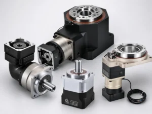
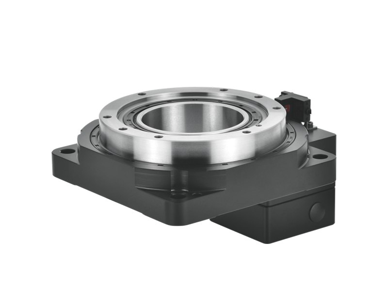
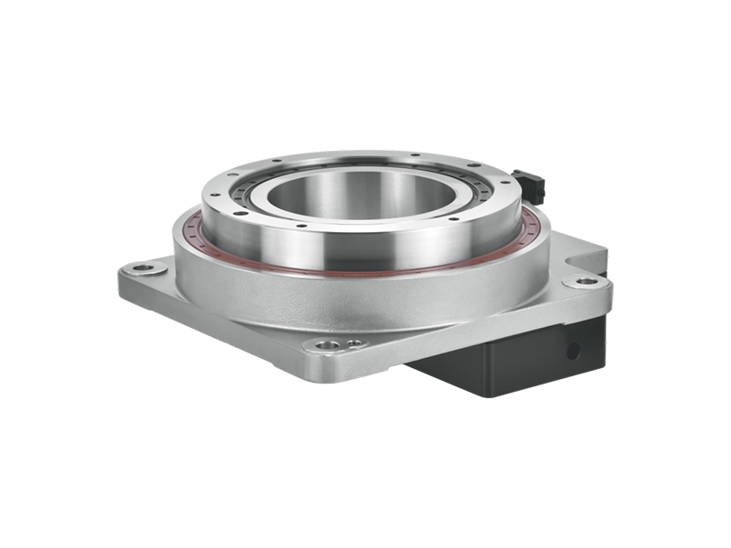
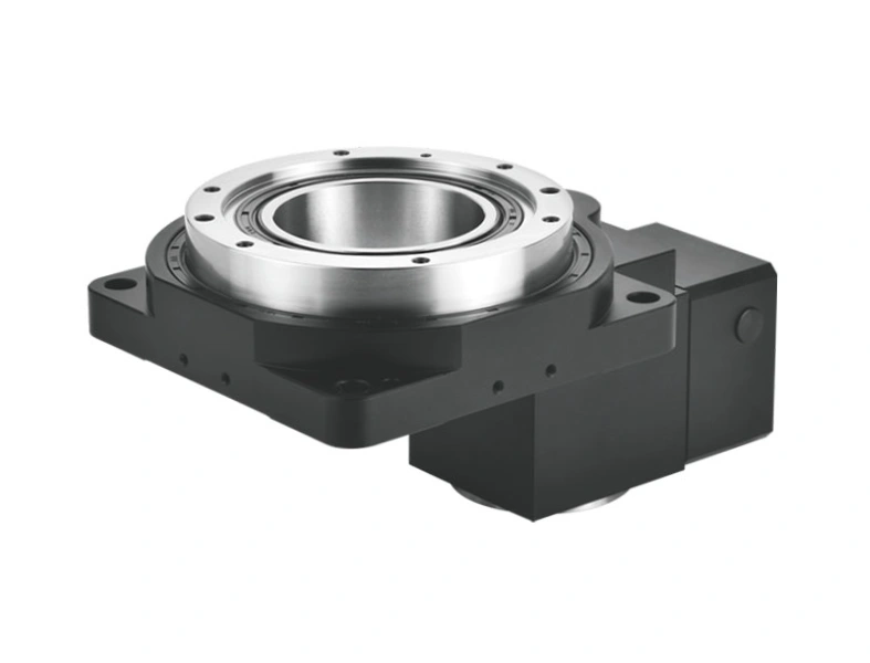
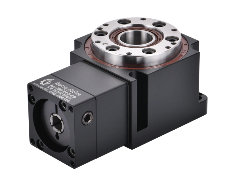
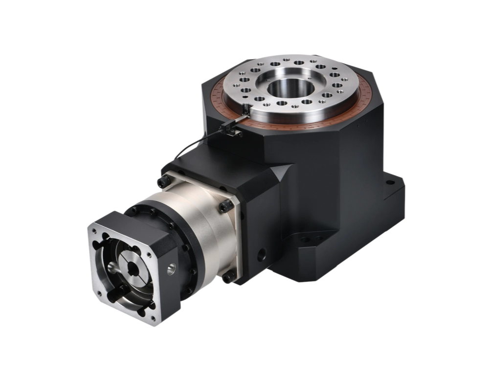
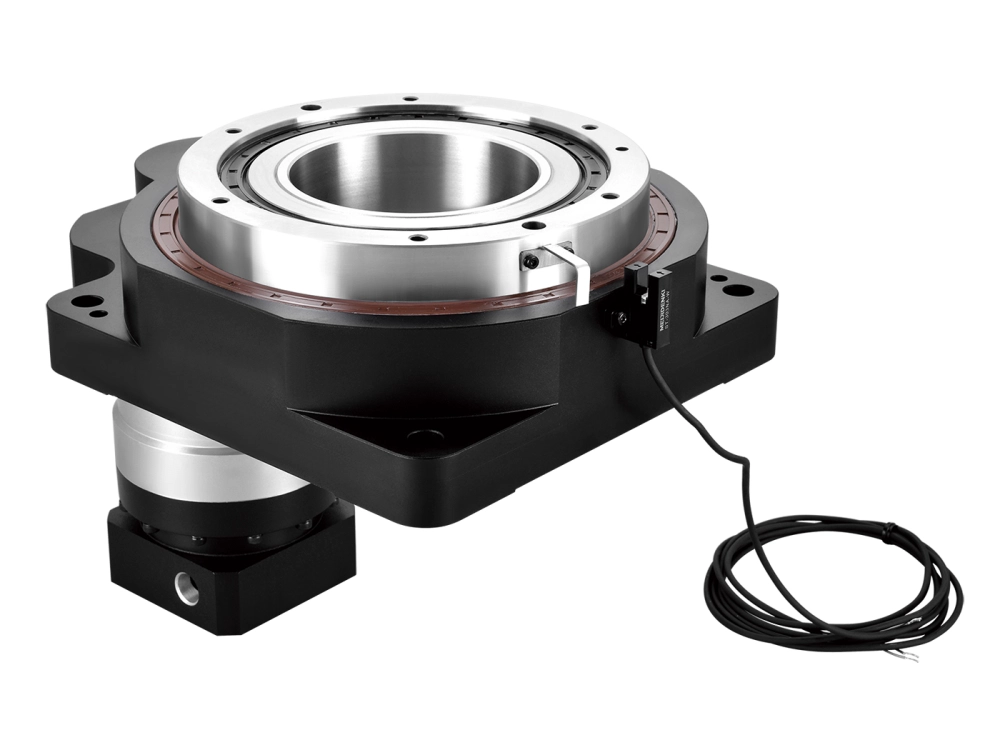
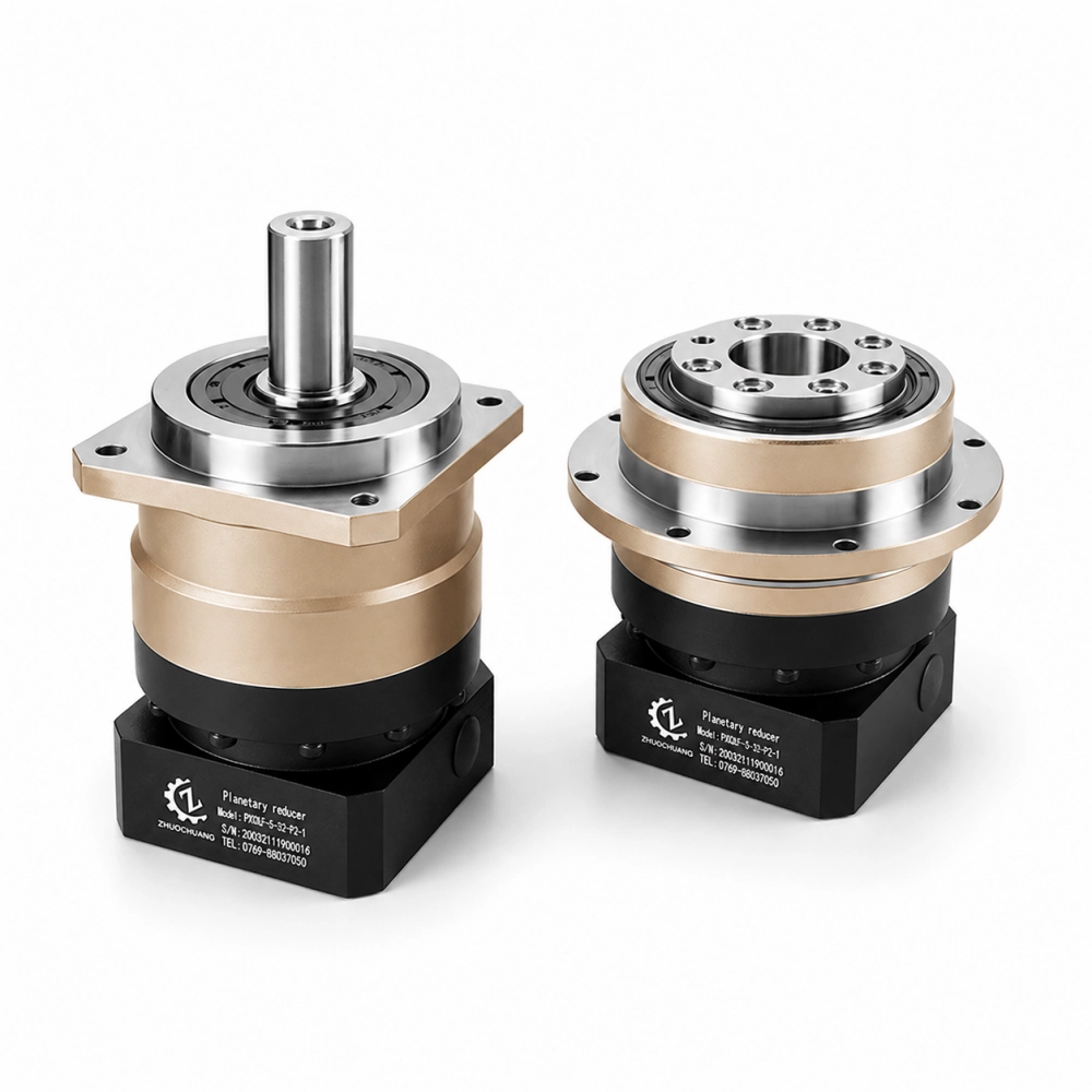
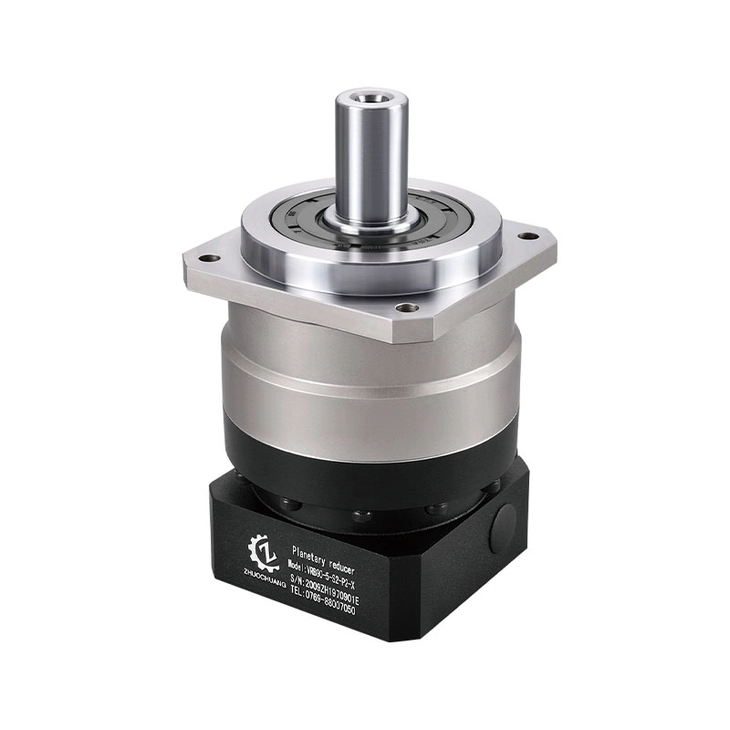
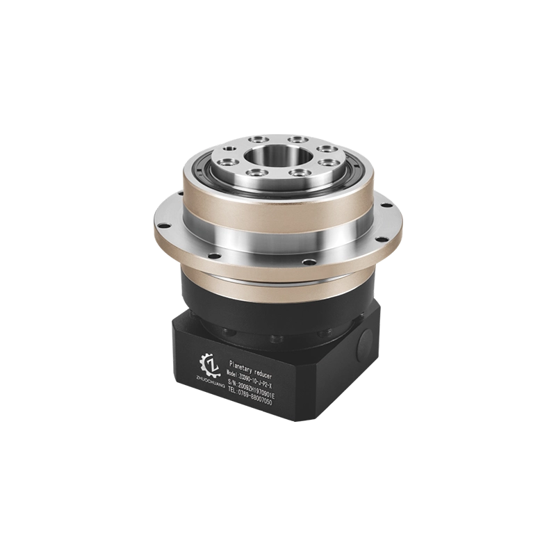
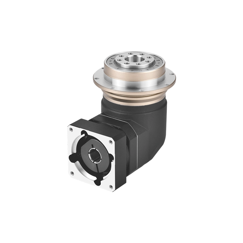
A flange mounted planetary gearbox provides a broad, short output interface that can connect directly to a machine component such as a pulley, pinion, rotary fixture or robot joint. Compared with a conventional projecting output shaft, the flange arrangement can shorten the mechanical connection, increase torsional rigidity and distribute fastening forces across multiple bolts.
Those benefits do not mean that every flange-style reducer can carry an unsupported machine load. The output bearing arrangement, allowable radial force, axial force and tilting moment still have to be checked. Buyers also need to distinguish the gearbox mounting flange from the rotating output flange. Confusing these two interfaces is one of the most common reasons that a reducer cannot be installed after delivery.
This guide explains how to evaluate a flange mounted planetary gearbox for servo automation, including robotic flange gear reducers, direct-load connections and compact motion axes.
What Is a Flange Mounted Planetary Gearbox?
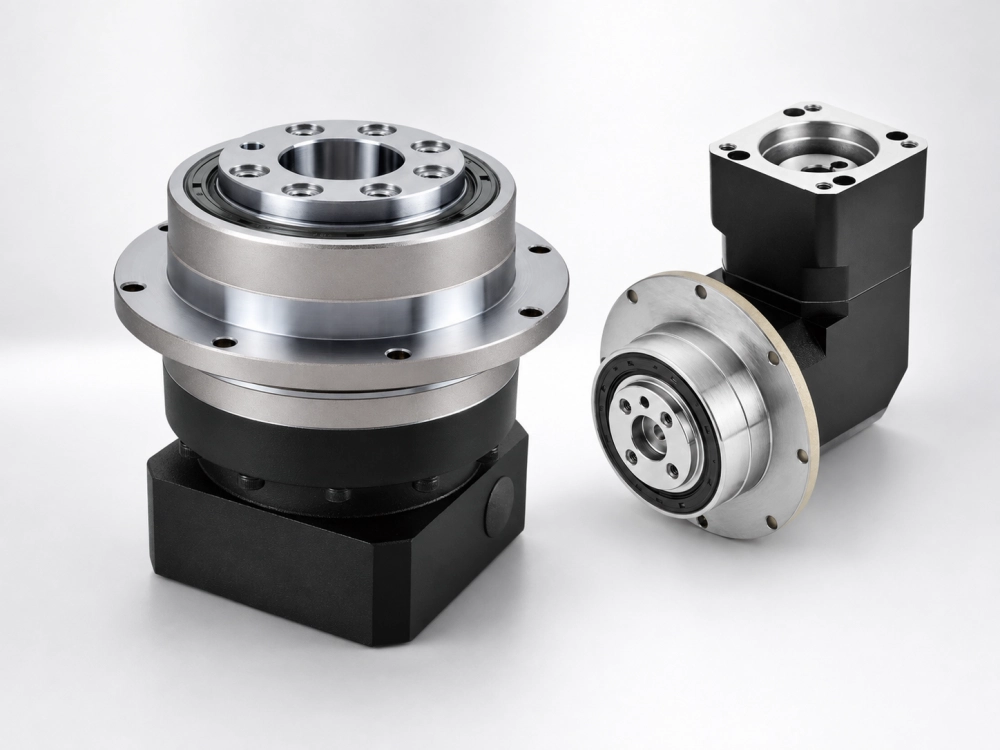
A flange mounted planetary gearbox is a planetary reducer that uses a flange-type interface for installation or output connection. In purchasing conversations, however, the term can describe two different features:
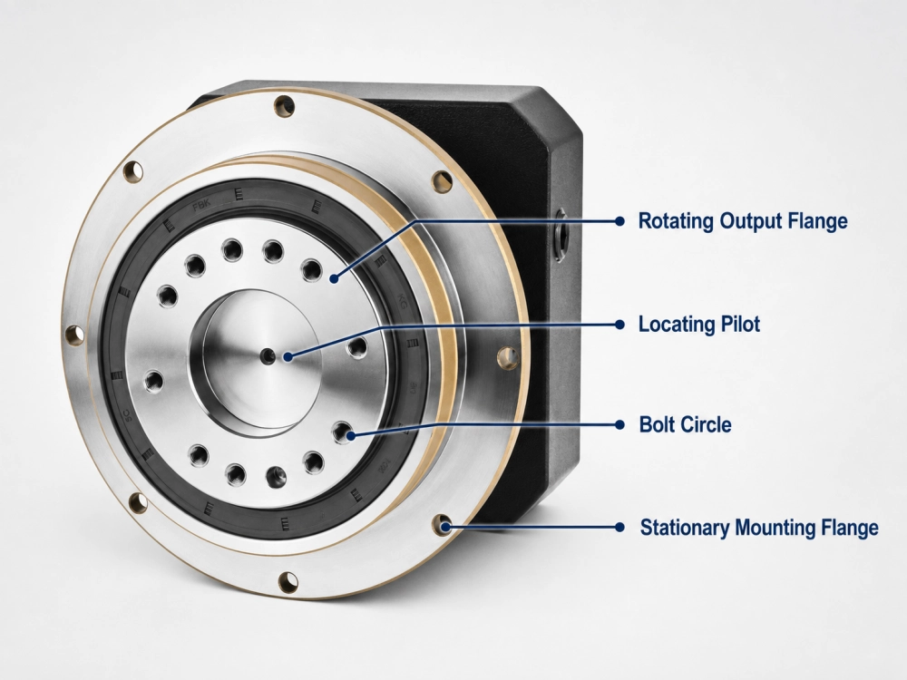
- Housing mounting flange: the stationary part used to bolt the gearbox housing to the machine frame.
- Output flange: the rotating part used to transmit torque to the driven component.
Many servo planetary gearboxes have an input-side mounting flange but still use a conventional output shaft. A true flange-output design has a rotating output face with a defined bolt pattern, pilot diameter and load-bearing structure. The buyer should therefore confirm which flange is being discussed rather than relying on the product name alone.
Inside the reducer, the planetary gear arrangement distributes load through multiple planet gears around a central sun gear. The output carrier transfers the reduced speed and increased torque to the output interface. When the carrier and output flange form a short, rigid structure, the connection can be more compact than an arrangement using a long projecting shaft, coupling and separate adapter.
If you first need an overview of output layouts, read our guide to planetary gearbox types.
Why Choose a Flange Output?
Shorter axial installation length
The short output geometry of a flange mounted planetary gearbox can reduce the distance between the reducer and the driven component. This is useful when a machine has limited axial space or when the designer wants to keep the load close to the output bearings.
Rigid torque connection
A large output diameter and multiple fastening points can produce a stiff connection. This helps a servo axis respond more consistently during acceleration, deceleration and reversal. It may also reduce the compliance introduced by extra couplings, keys and adapter parts.
Direct attachment of driven components
Depending on the gearbox design, a pulley, pinion, coupling hub, wheel or rotary mechanism may attach directly to the output flange. Direct mounting can simplify the assembly, but only when the gearbox bearing system is rated for the applied forces and moment load.
Repeatable mechanical alignment
A pilot diameter or locating shoulder can establish concentricity while the bolts provide clamping force. Correct use of the locating feature is more reliable than asking clearance bolts alone to center the driven part.
Flange gearboxes are commonly used in robotics, machine tools, rotary positioning systems and wheel drives where compact installation and a rigid output connection are important. However, the flange shape alone does not determine gearbox performance. Buyers must still verify torque, backlash, torsional stiffness, radial load, axial load and tilting moment for the individual model.
Where Robotic Flange Gear Reducers Fit
Robotic flange gear reducers are useful where a robot or automated handling axis needs a compact output connection, high torsional stiffness and repeatable motion. Possible applications include robot joints, end-of-arm positioning units, pick-and-place systems, portal handling axes and compact rotary fixtures.
The phrase robotic flange gear reducers describes an application group, not one universal gearbox standard. Some robotic systems use planetary reducers, while others use harmonic, cycloidal or specialized integrated joint drives. A flange mounted planetary gearbox should only be proposed when its backlash, torque, bearing loads, reduction ratio and geometry match the actual robot axis.
When evaluating robotic flange gear reducers, check the motion profile rather than only the robot payload. A modest payload can still create high peak torque when the arm is long, acceleration is fast or the load center is far from the gearbox. Emergency-stop torque, repeated reversal and external moment loads can be more severe than the steady operating condition.
Buyers should also avoid assuming that every robotic flange follows the same bolt pattern. ISO 9409-1 defines key dimensions and marking requirements for circular mechanical interfaces used with industrial robots, but compatibility must still be confirmed from the individual gearbox and machine drawings. The flange diameter, pilot, bolt-circle diameter, thread specification, hole depth and allowable moment all matter.
For these reasons, robotic flange gear reducers should be selected from an application drawing and load calculation—not from a photograph or frame-size name.
Key Selection Checks for a Flange Mounted Planetary Gearbox
1. Confirm the required output speed and ratio
Start with motor speed and required machine speed:
Required ratio = motor speed ÷ required output speed
Select an available ratio close to the calculated value, then confirm the resulting output speed. Do not force an exact theoretical ratio if the manufacturer does not offer it. Also confirm whether the selected ratio uses one or two planetary stages because this can affect efficiency, length, inertia and backlash.
2. Check continuous, acceleration and emergency torque
Rated output torque is not the only value that matters. A servo application can generate short acceleration peaks, reversal loads and emergency-stop torque. Compare the complete load cycle with the manufacturer’s nominal, cyclic and maximum allowable torque ratings. Apply an appropriate service factor for shock, duty cycle and operating environment.
3. Verify backlash and torsional stiffness
Backlash influences lost motion when the direction reverses. Torsional stiffness affects how much the drivetrain twists under load. A low-backlash specification alone does not guarantee a rigid or stable axis. For positioning machinery, both values should be evaluated with the servo tuning requirements and load inertia.
4. Calculate radial force, axial force and tilting moment
A wide flange may look capable of supporting a heavy load, but visual size is not a bearing rating. Calculate the forces created by belts, pinions, wheels and offset fixtures. The load distance from the output bearing is especially important because a longer overhung distance increases the tilting moment.
If the driven mechanism has its own bearings, determine how alignment and thermal expansion affect the gearbox. If it does not have separate support, obtain written confirmation that the selected flange mounted planetary gearbox can carry the full external load.
5. Match the servo motor interface
Provide the complete motor model. The supplier needs the motor flange dimensions, pilot diameter, bolt pattern, shaft diameter, shaft length and key or smooth-shaft details. Motor power alone is not enough because two motors with the same wattage may use different mechanical interfaces.
6. Check the output interface
Confirm:
- Output flange outside diameter
- Pilot or locating diameter and tolerance
- Bolt-circle diameter
- Number and size of threaded or clearance holes
- Thread depth and usable engagement
- Output face runout
- Permitted radial, axial and moment loads
- Required fastener grade and tightening torque
This is also where searches for speed reducer mounting brackets & flanges can become misleading. A separate stationary mounting bracket is not the same as a rotating torque-output flange. Identify the function of each part before comparing suppliers.
7. Review the operating environment
Temperature, contamination, washdown, mounting orientation, duty cycle and required service life can affect lubrication and seal selection. For food, clean-room or harsh industrial applications, confirm the required protection and material conditions rather than assuming a standard automation gearbox is suitable.
Use a Planetary Gearbox Assembly Drawing Before Ordering
A planetary gearbox assembly drawing should show more than the overall length and frame size. It should identify the input adapter, stationary mounting surface, rotating output flange, pilot diameters, bolt circles, thread details and shaft engagement.
Compare the drawing with the customer’s machine model or interface drawing. If only a PDF outline is available, verify every critical dimension instead of scaling the image. CAD data can help with interference checking, but the approved dimensional drawing should remain the controlling document.
For robotic flange gear reducers, the planetary gearbox assembly drawing should also be checked against cable routing, nearby joint components, tool access for bolts and the full swept envelope of the moving axis. A gearbox may fit statically but interfere with the machine during rotation.
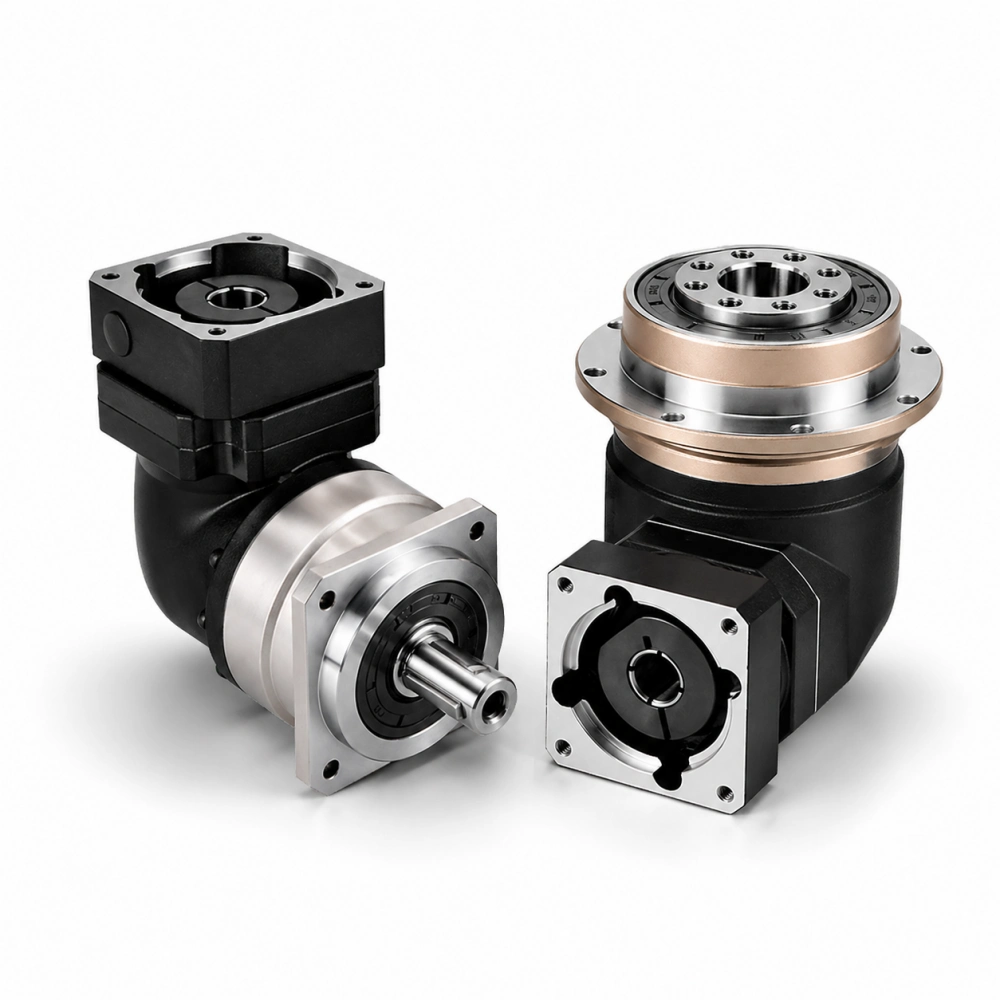
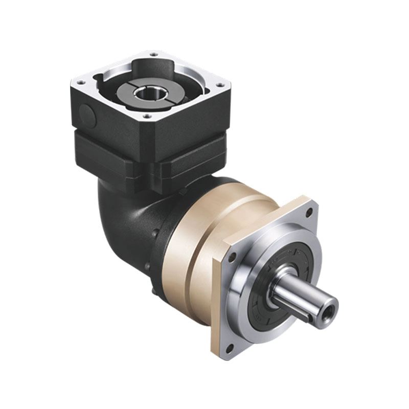
If the application needs a 90-degree motor arrangement, compare the interface with a right-angle planetary gearbox. Do not choose a right-angle layout only to save axial space without checking efficiency, backlash, installation access and output orientation.
Common Selection Mistakes
Confusing the mounting flange with the output flange
The housing flange is stationary. The output flange rotates. Mark both clearly on the drawing and confirm which one connects to the machine frame and which one drives the load.
Selecting by torque but ignoring moment load
A gearbox may have enough torque capacity but insufficient output-bearing capacity for an offset load. This is especially important for pulleys, pinions, robot arms and wheel drives.
Using bolts as the only centering feature
Clearance bolt holes do not provide accurate concentric positioning. Use the specified pilot or locating diameter and respect its tolerance.
Assuming all flange patterns are interchangeable
Similar-looking flanges may use different bolt circles, pilots, threads or hole depths. “Same frame size” does not prove dimensional interchangeability.
Adding unnecessary speed reducer mounting brackets & flanges
Extra adapter parts can increase axial length, tolerance stack-up and assembly cost. Use an additional bracket only when it is structurally required and supported by the gearbox mounting instructions.
Calling every robot reducer a planetary gearbox
Robotic flange gear reducers can use different internal reduction principles. Confirm the gearing type and performance data instead of choosing a planetary gearbox solely because the external flange looks suitable.
Where Zhuochuang Fits
Dongguan Zhuochuang Precision Machinery Co., Ltd. supplies precision planetary gearboxes and hollow rotary tables for industrial automation, CNC equipment, robotics, inspection systems and positioning machinery.
Our standard planetary gearbox families include different frame sizes, ratios, motor adapters and output structures. However, the phrase flange mounted planetary gearbox can refer to several mechanical arrangements. Product suitability must therefore be confirmed from the required output interface and load data rather than assumed from the keyword.
Where a standard model does not match, our team can review the motor drawing, machine interface, torque, speed, backlash and quantity to determine whether an available configuration or practical customization is possible. We will not describe a product as a robotic flange solution unless its drawing and load ratings fit the application.
Information to Send for an Accurate Recommendation
For selection and quotation support, please provide:
- Servo or stepper motor brand and complete model
- Motor rated speed, rated torque and peak torque
- Required output speed or reduction ratio
- Continuous, acceleration and emergency-stop torque
- Required backlash and positioning performance
- Radial force, axial force and tilting moment
- Load distance from the output mounting face
- Required output flange drawing or machine-side drawing
- Mounting orientation, duty cycle and environment
- Required quantity and project schedule
Frequently Asked Questions
What is a flange mounted planetary gearbox?
It is a planetary reducer with a flange-type mounting or output interface. For accurate selection, confirm whether “flange mounted” refers to the stationary housing flange or the rotating output flange.
Can a flange output connect directly to the machine load?
Sometimes. Direct attachment is possible when the bolt pattern, pilot, bearing capacity, radial force, axial force and tilting moment ratings all suit the load. A flange shape alone does not prove that separate load support is unnecessary.
Are robotic flange gear reducers always planetary gearboxes?
No. Robots may use planetary, harmonic, cycloidal or other specialized reducers. The correct choice depends on torque, backlash, stiffness, size, ratio, duty cycle and output-bearing requirements.
What dimensions are needed to replace an existing flange gearbox?
Provide the complete planetary gearbox assembly drawing or measure the input adapter, housing mounting pilot, bolt patterns, output flange, output pilot, overall length and shaft engagement. Torque and load ratings must also be compared; dimensional fit alone is insufficient.
Is a flange mounted gearbox better than a shaft-output gearbox?
Neither structure is universally better. A flange output may provide a short, rigid and convenient direct connection. A shaft output may be simpler for couplings, pulleys or mechanisms already designed around a keyed or clamped shaft.
Can a flange mounted planetary gearbox be used with a servo motor?
Yes, when the adapter matches the motor shaft and flange and the reducer satisfies the ratio, torque, speed, inertia, backlash, stiffness and duty-cycle requirements.
Final Selection Rule
Choose a flange mounted planetary gearbox from the complete mechanical interface and load case—not from the flange diameter or catalog picture. Confirm which flange rotates, how the driven component is centered, what forces reach the output bearings and whether the motor adapter is correct.
For robotics and compact automation, the best robotic flange gear reducers are not simply the models with the widest output face. They are the models whose torque, stiffness, backlash, bearing capacity and planetary gearbox assembly drawing match the real machine.