
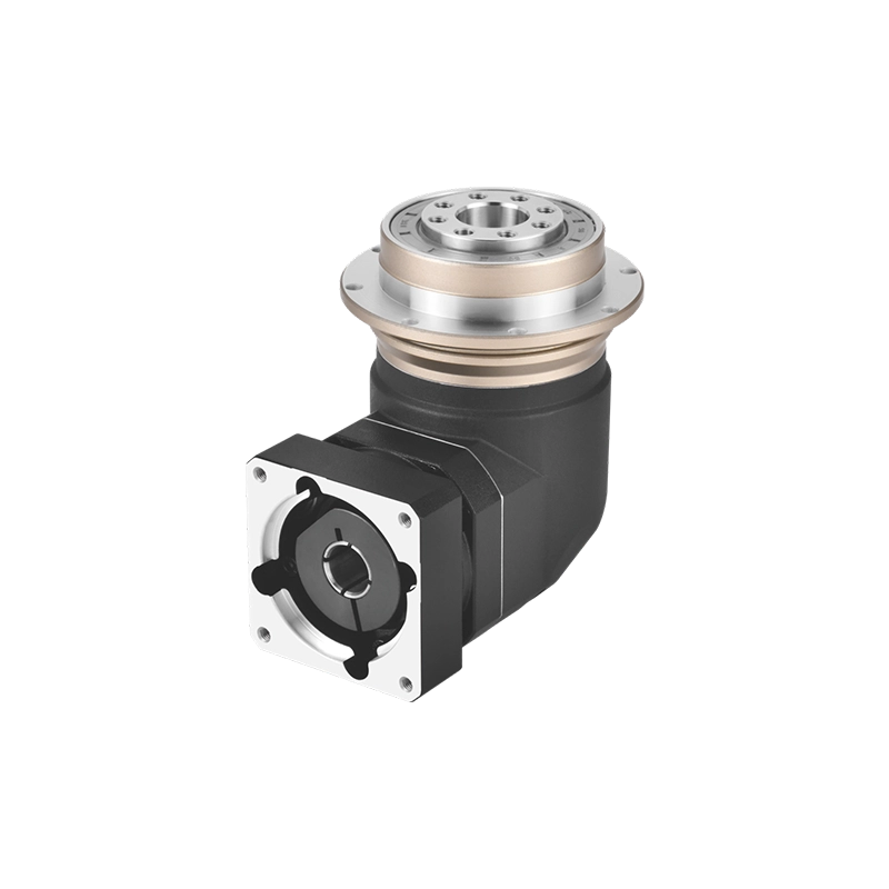
Gear Reducer Ratio Mistakes That Affect Machine Performance
Gear reducer ratio looks like a simple number.
A buyer may ask for a 5:1 reducer, a 10:1 reducer, a 25:1 reducer, or a 50:1 reducer. A designer may calculate motor speed divided by output speed and assume the selection is finished.
But in real industrial automation, gear reducer ratio is not only a speed reduction number.
It affects motor operating speed, output torque, acceleration, load inertia, heat, efficiency, positioning response, machine cycle time, and long-term service life.
Many gearbox selection problems do not start from poor gearbox quality. They start from the wrong ratio.
This article explains common gear reducer ratio mistakes and how to avoid them when selecting reducers for servo automation, CNC machinery, packaging equipment, conveyors, indexing systems, and precision motion equipment.
Gear Reducer Ratio Is Not Just Output Speed
The basic ratio idea is easy to understand.
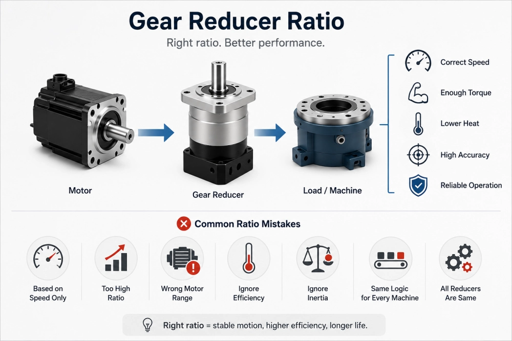
If a motor runs at 3000 rpm and the gearbox ratio is 10:1, the theoretical output speed is about 300 rpm before considering slip, load behavior, and control limits.
In simple form:
Output speed = Motor speed ÷ Gear reducer ratio
And in an ideal system:
Output torque = Motor torque × Gear reducer ratio
But real machines are not ideal systems.
Efficiency loss, acceleration load, inertia mismatch, duty cycle, backlash, mounting structure, and motor control behavior all change the final result.
This is why selecting a gear reducer ratio only from required output speed can lead to wrong reducer selection.
Practical rule: Ratio selection should begin with output speed, but it should never end there.
Mistake 1: Choosing Ratio Only from Output Speed
The most common mistake is simple:
The motor speed is known. The required output speed is known. The buyer divides one number by the other and chooses a reducer ratio.
For example:
3000 rpm motor ÷ 300 rpm output = 10:1 ratio
This calculation is useful, but it does not confirm whether 10:1 is the best ratio.
The machine may also need:
- Enough output torque
- Fast acceleration
- Stable servo response
- Low heat generation
- Controlled backlash
- Correct inertia matching
- Acceptable motor operating speed
If the ratio is chosen only by final speed, the motor may run outside its best performance range, or the gearbox may not provide enough usable torque during acceleration.
A better approach is to calculate required output speed first, then check torque, inertia, motor speed range, efficiency, duty cycle, and positioning requirement together.
Mistake 2: Assuming Higher Ratio Always Means More Useful Torque
A higher gear reducer ratio can multiply torque, but that does not mean a higher ratio is always better.
Higher ratio usually means lower output speed. In some machines, that can slow the cycle time too much.
Higher ratio can also increase reflected inertia benefits, but it may reduce dynamic response if the system becomes too slow or if the motor cannot operate efficiently in the selected speed range.
There is also efficiency loss. A high-ratio reducer may require multiple stages, and each stage adds mechanical loss.
The problem is not that high ratio is bad.
The problem is choosing high ratio only because the torque number looks attractive.
For servo-driven machines, ratio should be selected to balance torque multiplication, output speed, inertia matching, efficiency and response.
Mistake 3: Ignoring Motor Speed Range
A gear reducer does not work alone. It works with a motor.
If the ratio is too low, the motor may need to produce too much torque at low speed. This can create heat or overload problems.
If the ratio is too high, the output may become too slow, and the motor may run in a speed range that does not match the desired machine cycle.
For servo motors, the usable operating area includes speed, continuous torque, peak torque, and thermal capacity.
A correct gear reducer ratio should allow the motor to run in a stable and efficient range while still producing the required output speed and torque.
This is especially important in:
- High-speed packaging axes
- Pick-and-place systems
- CNC feed mechanisms
- Servo indexing systems
- Robotic auxiliary axes
- Automated assembly equipment
Choosing the reducer ratio without checking the motor curve can cause poor acceleration, overheating, vibration, or slow cycle time.
Mistake 4: Forgetting Efficiency Loss
In theory, torque increases with ratio. In reality, efficiency reduces the usable output torque.
The more gear stages the reducer uses, the more efficiency loss must be considered.
For example, a single-stage reducer may have higher efficiency than a two-stage reducer. A three-stage reducer may provide a much higher ratio, but it also generates more heat.
This does not mean multi-stage reducers should be avoided. It means the ratio should justify the extra stages.
If a machine needs a ratio that cannot be achieved by one stage, a two-stage or multi-stage gearbox may be correct. But if the ratio is only slightly higher than necessary, overspecifying ratio can create avoidable efficiency and heat problems.
For a deeper explanation of stage count, see:
Multistage Planetary Gearbox: 2-Stage and 3-Stage Selection Guide
Mistake 5: Ignoring Load Inertia
In servo applications, gear reducer ratio affects reflected inertia.
This is one reason reducers are widely used with servo motors. A suitable ratio can make a high-inertia load easier for the motor to control.
But the ratio must be selected carefully.
If the ratio is too low, the motor may struggle to accelerate and decelerate the load.
If the ratio is too high, the output speed may become too low, and the system may lose the required response.
The best ratio is not always the highest ratio. It is the ratio that helps the motor control the load while maintaining the required output speed and machine cycle.
This is why a servo reducer should be selected with motor data, load inertia, acceleration time, and motion profile, not only with output speed.
Mistake 6: Using the Same Ratio Logic for Every Machine
A conveyor, a CNC axis, a rotary indexer, and a packaging machine may all use gear reducers, but they do not select ratio in the same way.
| Application | Ratio Priority | Main Risk |
|---|---|---|
| Conveyor drive | Output speed and continuous torque | Overheating or insufficient torque |
| CNC axis | Servo response and positioning accuracy | Poor dynamic control or backlash error |
| Rotary indexer | Positioning repeatability and peak torque | Overshoot, vibration or long settling time |
| Packaging machine | Cycle speed and frequent acceleration | Slow cycle time or thermal overload |
| Robot auxiliary axis | Inertia matching and compact structure | Unstable motion or oversized reducer |
This is why gear reducer ratio should be selected according to the machine function.
A ratio that works well in a slow conveyor may not work well in a fast servo positioning system.
Mistake 7: Treating All Reducer Types the Same
The same ratio can behave differently depending on reducer type.
A worm reducer, cycloidal reducer, helical reducer, and planetary gearbox may all offer similar reduction ratios, but they differ in efficiency, backlash, stiffness, size, heat, cost, and servo response.
For simple low-speed transmission, several reducer types may be acceptable.
For precision servo automation, the reducer must also support dynamic motion, low backlash, stiffness, and motor compatibility.
This is where a precision planetary gearbox often becomes a practical option.
It can provide compact size, high torque density, good efficiency, low backlash options, and direct servo motor matching.
For more detail about planetary gearbox types, see:
Planetary Gearbox Types: Inline, Right-Angle and Output Designs
How to Discuss Gear Reducer Ratio with a Supplier
When asking a supplier for a gear reducer ratio recommendation, do not only say “I need 10:1” or “I need 30:1.”
Send the application data that explains why the ratio is needed.
Useful information includes:
- Motor type and model
- Motor rated speed
- Motor continuous and peak torque
- Required output speed
- Required output torque
- Load inertia
- Acceleration and deceleration time
- Duty cycle
- Backlash target
- Mounting direction
- Output load condition
- Machine cycle requirement
- Working environment
With this information, the supplier can confirm whether the requested ratio is reasonable or whether a nearby ratio would improve performance.
Where Planetary Gearboxes Fit
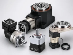
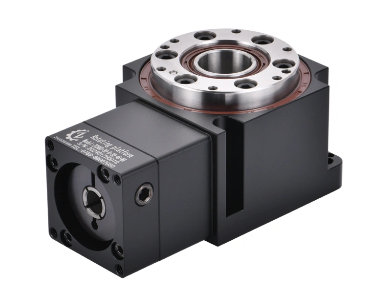
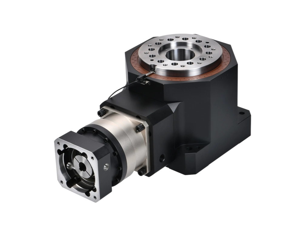
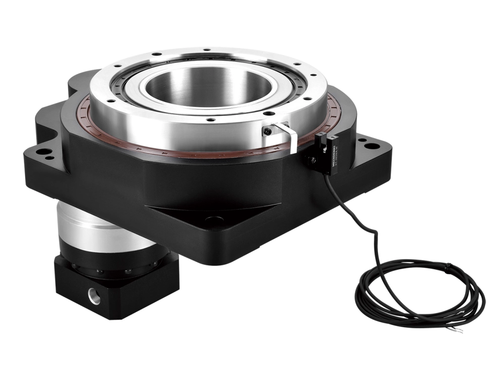
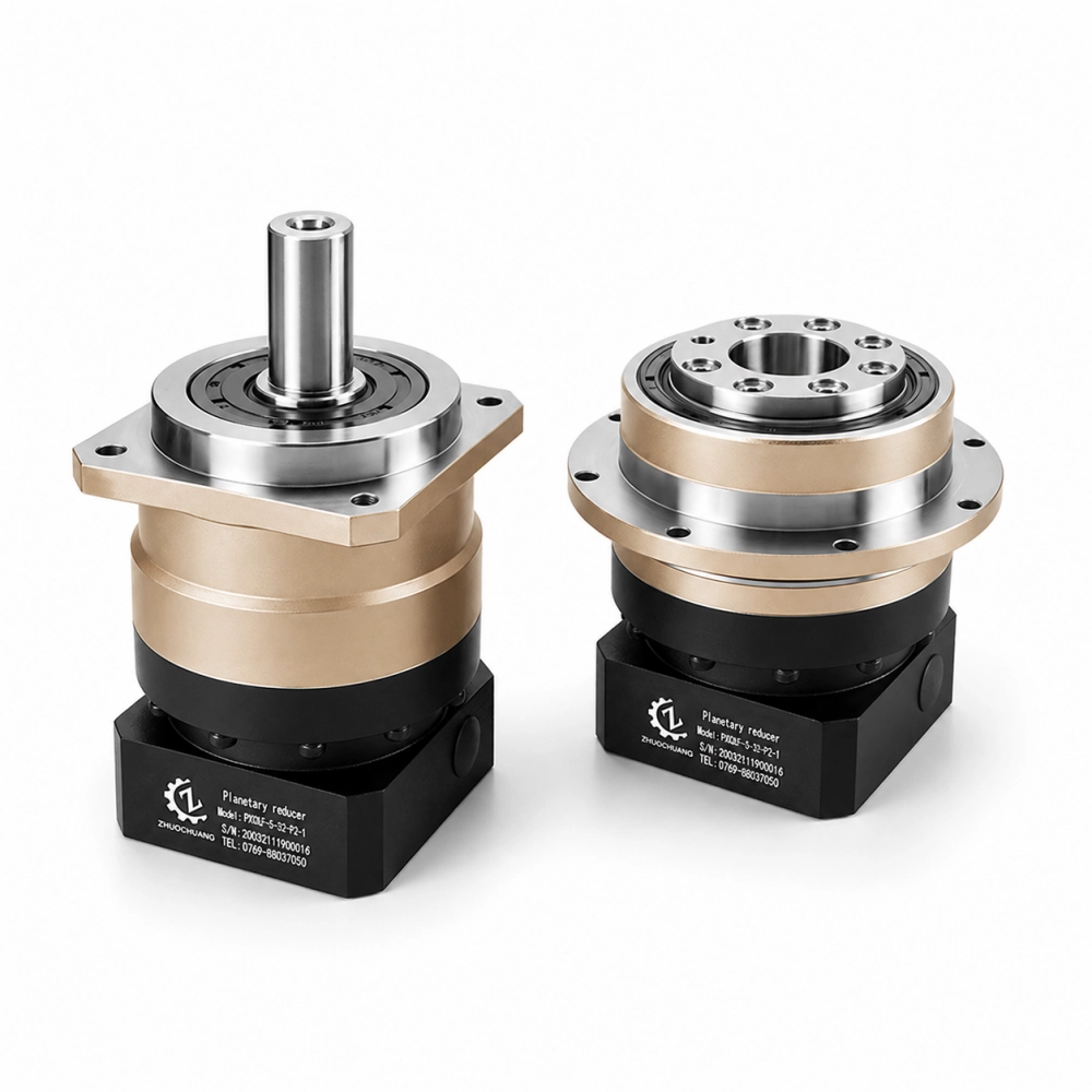
Dongguan Zhuochuang Precision Machinery Co., Ltd manufactures precision planetary gearboxes for servo automation, CNC machinery, robotics, packaging equipment, and industrial positioning systems.
For many industrial applications, the ratio decision is closely connected with gearbox type.
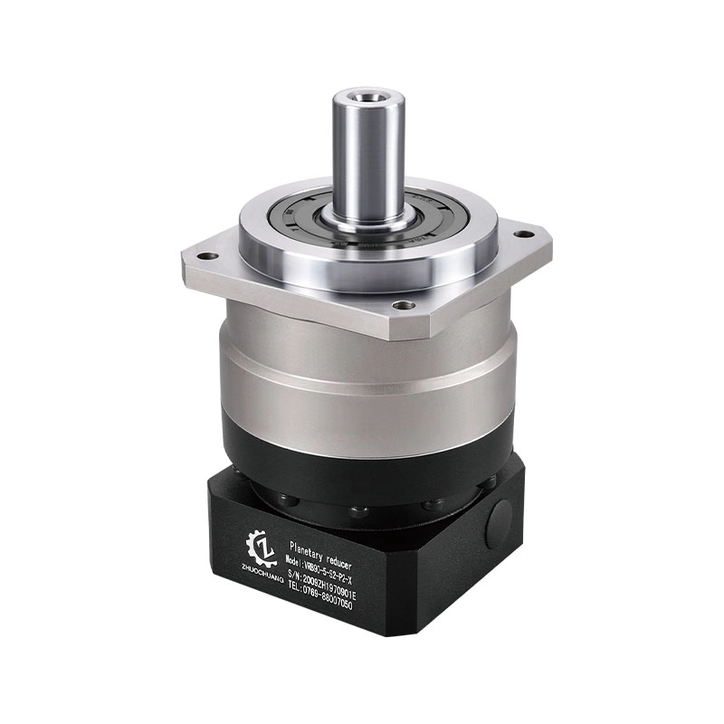
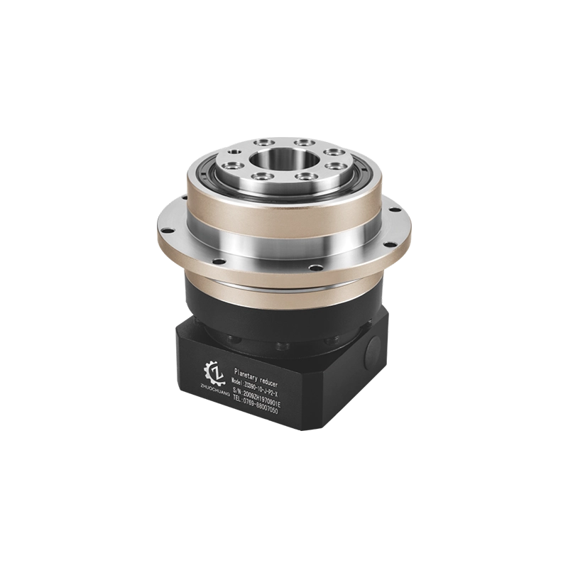
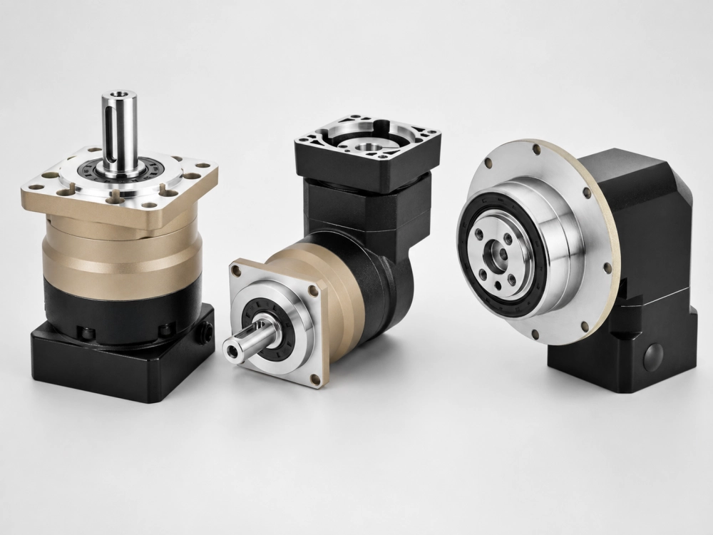
If the motor and output shaft are aligned, an inline planetary gearbox may be suitable.
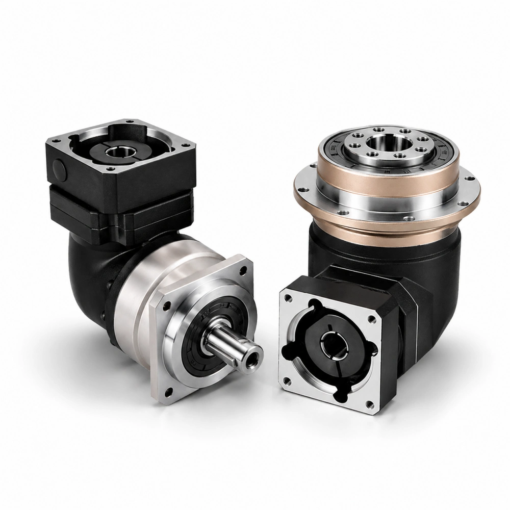
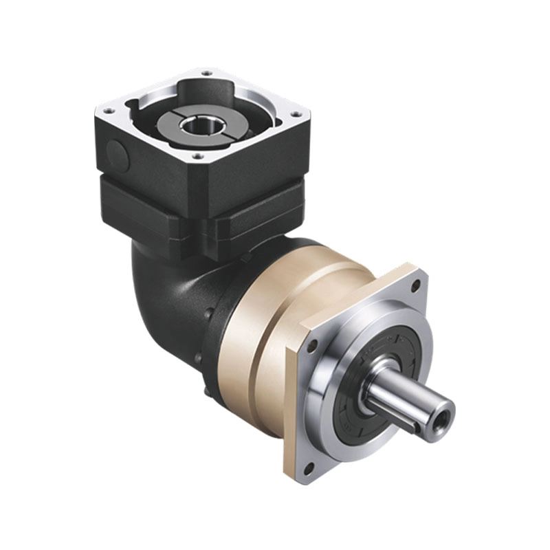
If the machine needs a 90-degree layout, a right-angle planetary gearbox may save installation space.
If the required ratio is higher than a single stage can provide, a two-stage or multistage planetary gearbox may be considered.
If the machine requires repeatable positioning, backlash and stiffness should be checked together with ratio.
You can view Zhuochuang planetary gearbox products here:
Precision Planetary Gearbox Range
For same-axis servo layouts:
For space-limited 90-degree layouts:
For technical selection support:
Quick Ratio Selection Checklist
Before confirming a gear reducer ratio, check these points:
- Does the ratio provide the required output speed?
- Does the motor still operate in a good speed range?
- Is the output torque enough after efficiency loss?
- Does the ratio improve load inertia matching?
- Will the machine cycle time still be acceptable?
- Does the ratio require one stage, two stages, or more?
- Will additional stages create heat or efficiency concerns?
- Is the backlash suitable for the positioning requirement?
- Is the gearbox frame size strong enough for the load?
- Does the selected reducer type match the machine layout?
Final Thought
Gear reducer ratio should not be selected as an isolated number.
The correct ratio affects output speed, torque, efficiency, inertia, heat, backlash, motor performance and machine response.
A ratio that looks correct in a simple calculation may still cause problems if the motor speed range, load inertia, duty cycle or reducer type is ignored.
For industrial automation, the best gear reducer ratio is not always the highest ratio or the most common catalogue option. It is the ratio that allows the motor, gearbox and machine load to work together reliably.