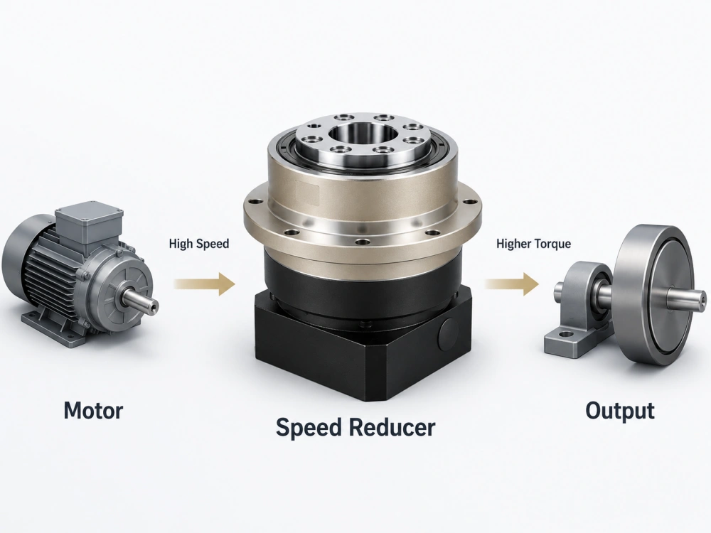
A speed reducer is a mechanical device that takes rotational input from a motor, reduces its speed, and delivers higher usable torque at the output.
That is the simple answer.
The more practical answer is this: a speed reducer helps a motor work in the range where it performs well, while allowing the machine to move at the speed and force it actually needs. In industrial equipment, this small-looking component often decides whether a conveyor runs steadily, a rotary table indexes accurately, a robot joint moves smoothly, or an automation line repeats the same motion thousands of times without trouble.
A speed reducer does not create power from nothing. It converts speed into torque through mechanical reduction. The motor sends power into the reducer at a relatively high speed. The reducer lowers the output speed and increases the turning force, with a small amount of energy lost through friction and heat.
This article explains what a speed reducer does, why industrial machines need it, how speed reduction changes torque, what reducer designs are commonly used, and what information should be checked before choosing one for a real machine.
Why Industrial Machines Need Speed Reducers
Electric motors usually prefer to run fast. Depending on the motor type and design, many industrial motors operate efficiently at hundreds or thousands of revolutions per minute.
Industrial machines do not always want that kind of speed.
A conveyor belt may need slow, stable movement. A rotary table may need to index 90 degrees in a controlled time. A robot joint may need to move a payload smoothly without vibration. A packaging machine may need repeated motion at a fixed rhythm. A CNC auxiliary axis may need accurate positioning instead of raw speed.
This creates a mismatch between the motor and the load.
If a motor were connected directly to a heavy load at low speed, the motor would often need to be much larger to provide enough torque. That increases cost, size, weight, and control difficulty. A speed reducer solves this problem by allowing the motor to run at a suitable speed while the output side delivers slower, stronger motion.
This is why speed reducers are used across automation equipment, robotics, packaging lines, CNC machinery, material handling systems, and many other industrial machines.
Speed Reduction Means More Usable Torque
The basic relationship is easy to understand.
When output speed decreases through a reducer, output torque increases in proportion to the reduction ratio, minus efficiency losses.
For example, if a motor runs at 3,000 RPM and the machine needs 150 RPM at the output, a 20:1 reducer can bring the speed down close to the required range. If the motor provides 5 Nm of torque, the theoretical output torque after reduction would be close to 100 Nm before losses. With gearbox efficiency considered, the real output may be slightly lower.
The reducer does not magically add energy. It changes the form of the motor’s power into something more useful for the load.
This is one of the main reasons industrial machines use reducers. A smaller motor can drive a heavier load when the speed is reduced properly. The machine also becomes easier to control because the reducer helps match motor speed, output speed, and load demand.
What a Speed Reducer Actually Does in a Machine
A speed reducer usually sits between the motor and the driven component. The motor connects to the input side. The output side connects to the machine shaft, pulley, rotary table, actuator, conveyor, or other driven mechanism.
In practice, the reducer performs several functions at the same time.
It reduces motor speed to a usable output speed.
It increases output torque so the machine can move the load.
It helps match motor performance to the working requirement.
It can improve motion control by reducing the load reflected back to the motor.
It may change the direction of transmission, depending on the reducer structure.
It can make the machine more compact by avoiding oversized direct-drive motors.
For simple machines, the reducer may only need to provide speed reduction and torque increase. For servo-driven automation, the reducer may also need low backlash, high stiffness, smooth transmission, and accurate motor matching.
This is why reducer selection should not be based only on ratio. The same ratio can perform very differently depending on gear design, precision grade, housing rigidity, bearing support, lubrication, and manufacturing quality.
Speed Reducer, Gear Reducer and Gearbox: Are They the Same?
In many industrial conversations, the terms speed reducer, gear reducer, and gearbox are used in similar ways. They overlap, but they do not always emphasize the same thing.
“Speed reducer” describes the function. It focuses on reducing speed and increasing usable torque.
“Gear reducer” usually means the reduction is achieved by gears.
“Gearbox” describes the mechanical assembly. It includes gears, shafts, bearings, housing, seals, lubrication, and mounting interfaces.
In practical purchasing, a buyer may search for a speed reducer, gear reducer, planetary gearbox, servo reducer, right angle reducer, or industrial gearbox depending on the application and local naming habit.
For suppliers and engineers, the important question is not only which word is used. The important question is what the machine needs: output speed, torque, precision, mounting style, duty cycle, and service life.
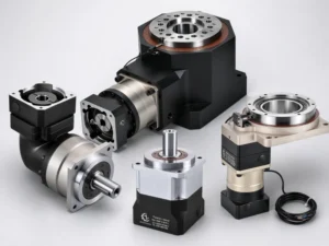
Common Industrial Reducer Designs and Why They Differ
Different speed reducer designs exist because machines create different mechanical problems. Some applications need compact high torque. Some need low cost. Some need a 90-degree transmission layout. Some need shock resistance. Some need low backlash for servo positioning.
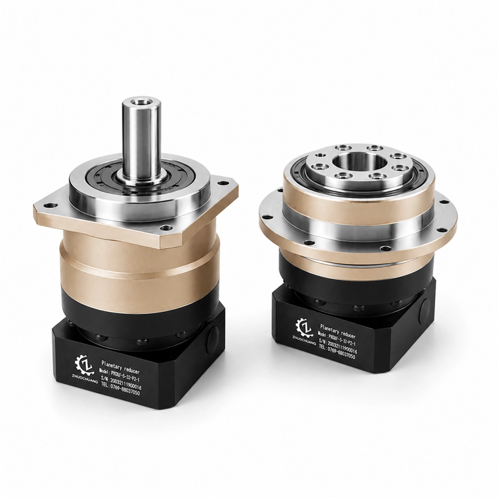
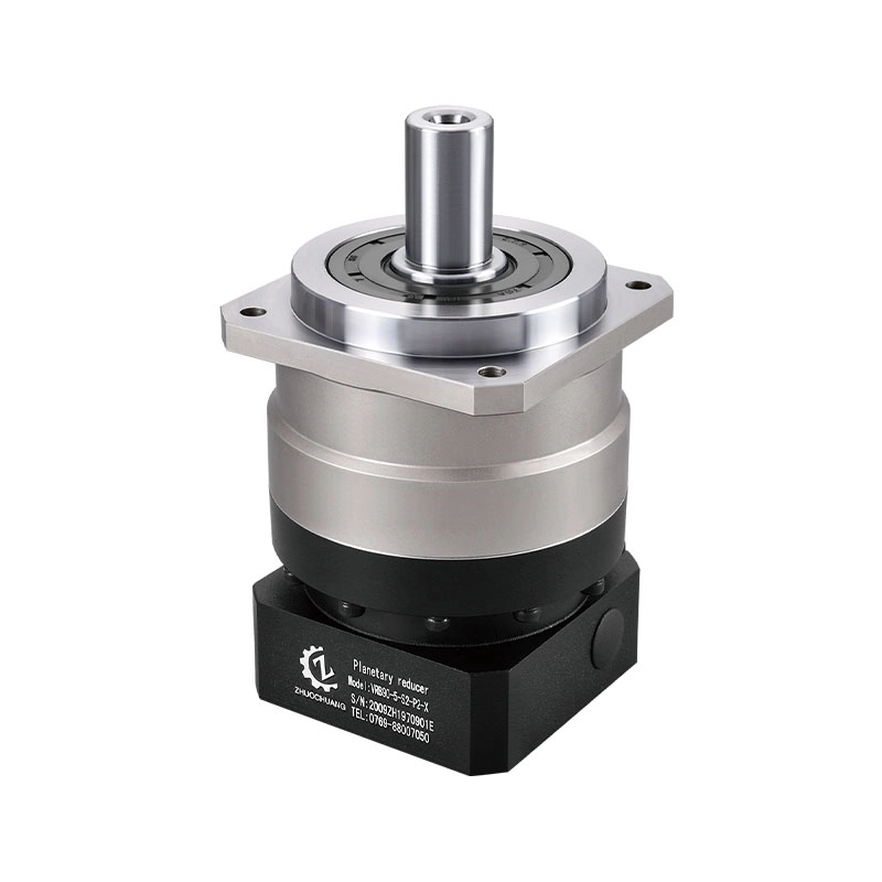
Planetary Reducer
A planetary reducer uses a sun gear, planet gears, ring gear, and planet carrier. Several planet gears share the load at the same time, which gives this design high torque density in a compact housing.
Planetary reducers are often selected when a machine needs compact size, controlled motion, high torque density, and good compatibility with servo motors.
In automation, robotics, CNC machinery, packaging systems, and precision positioning, planetary reducers are common because they can support low backlash and high torsional stiffness when manufactured to precision grade.
This does not mean planetary reducers are always the best answer for every machine. For large steady-load conveyors or simple general-purpose equipment, other reducer types may be more cost-effective. But for servo-driven equipment where space, precision, and repeatability matter, planetary reducers are often worth evaluating.
You can view Zhuochuang’s precision planetary gearbox range for automation and motion control applications.
Helical and Parallel-Shaft Reducers
Helical reducers usually use parallel shafts with angled gear teeth. The angled tooth profile allows smoother engagement than straight spur gears, helping reduce noise and vibration.
These reducers are widely used in general industrial machinery, especially where the machine has enough installation space and the main requirement is reliable power transmission rather than compact precision positioning.
Helical reducers are common in conveyors, mixers, processing equipment, and heavy industrial machinery. They are mature, practical, and available in many sizes.
Worm Reducers
A worm reducer uses a worm shaft and worm wheel. This design can provide high reduction ratios in a compact structure and naturally creates a right-angle output.
Worm reducers are often used where the machine needs a 90-degree layout or where the load must resist back-driving. Some worm reducers can help hold position when the motor stops, depending on the ratio and design.
The tradeoff is efficiency. Worm gear contact involves more sliding friction than many other gear types, so heat and energy loss can be higher. For precision servo positioning, worm reducers are usually not the first choice because low-speed smoothness and efficiency can become concerns.
Cycloidal Reducers
Cycloidal reducers use eccentric motion and cycloidal tooth engagement. They can handle high reduction ratios and strong shock loads in a compact structure.
This makes them useful in heavy-duty robot joints, presses, indexing tables, and applications with repeated impact or shock loading.
However, cycloidal reducers can cost more than standard alternatives. They are most suitable when shock load resistance is truly important, not just when a high ratio is needed.
Bevel and Hypoid Reducers
Bevel and hypoid gear designs are often used when the drive direction needs to change, commonly by 90 degrees.
A bevel reducer uses conical gear geometry to redirect motion. A hypoid reducer uses offset shaft centerlines, which can allow more compact packaging and different tooth engagement characteristics.
These designs are often used in right-angle transmission arrangements. They may be used alone or combined with other reduction stages, including planetary structures.
How Speed Reducers Are Mounted in Machines
The internal reduction mechanism is only one part of the selection. The way the reducer is mounted also matters.
A flange-mounted reducer bolts directly to a machine frame, motor bracket, or mounting plate. This is common in automation equipment and servo-driven machinery.
A shaft-mounted reducer fits directly onto the driven shaft. It is often used in conveyors, mixers, and material handling equipment. This can simplify installation because it reduces the need for separate coupling and alignment work.
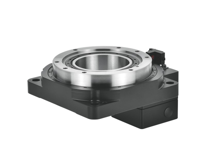
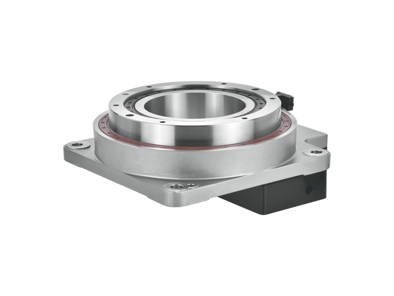
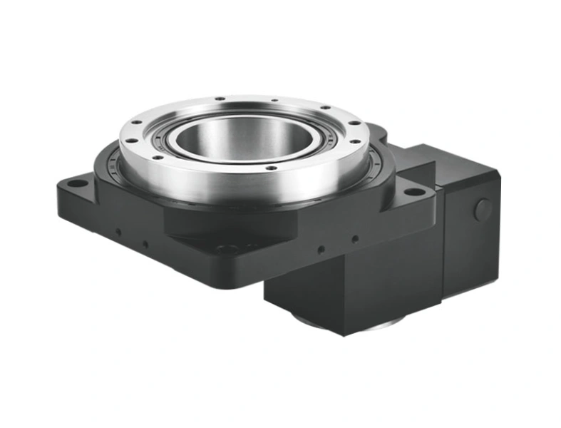
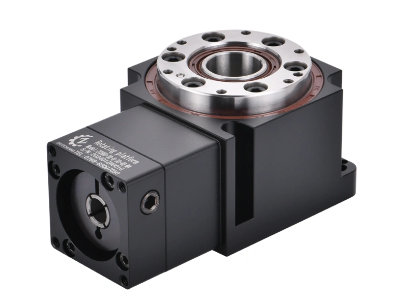
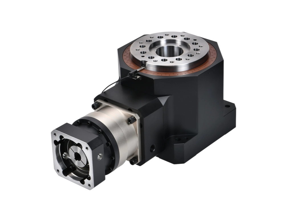
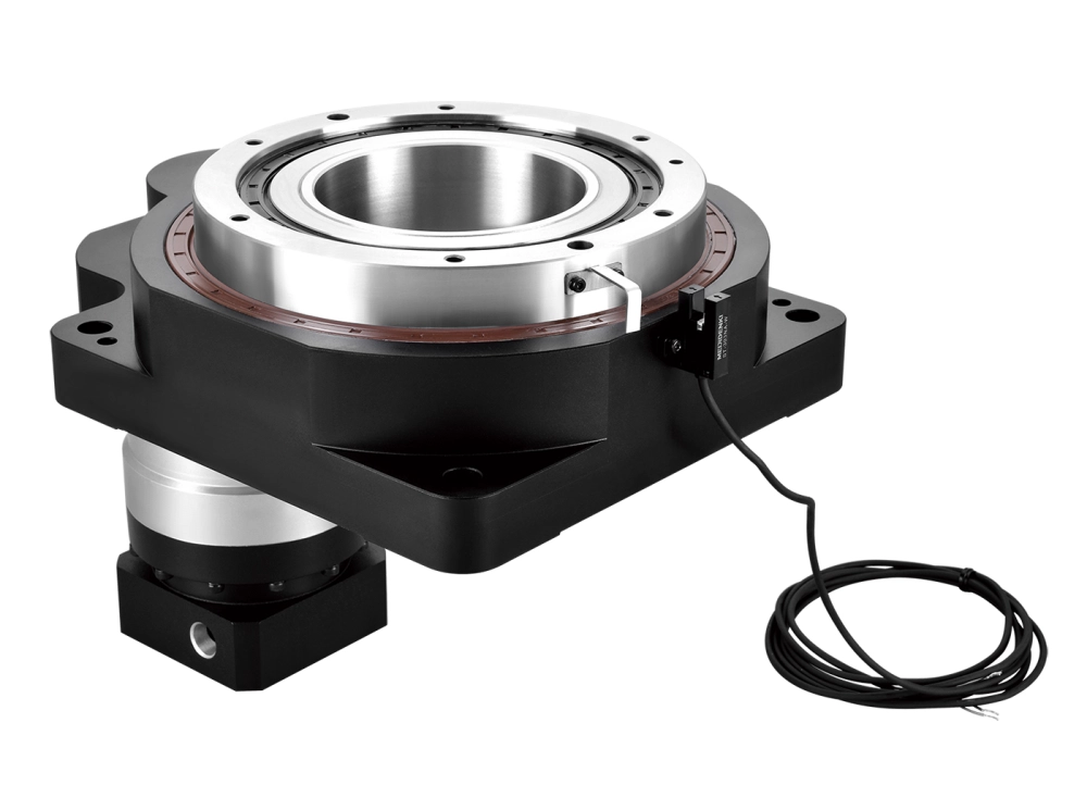
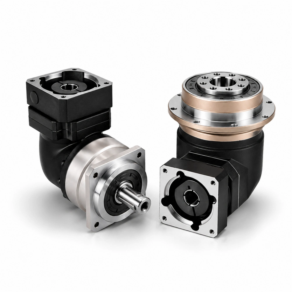
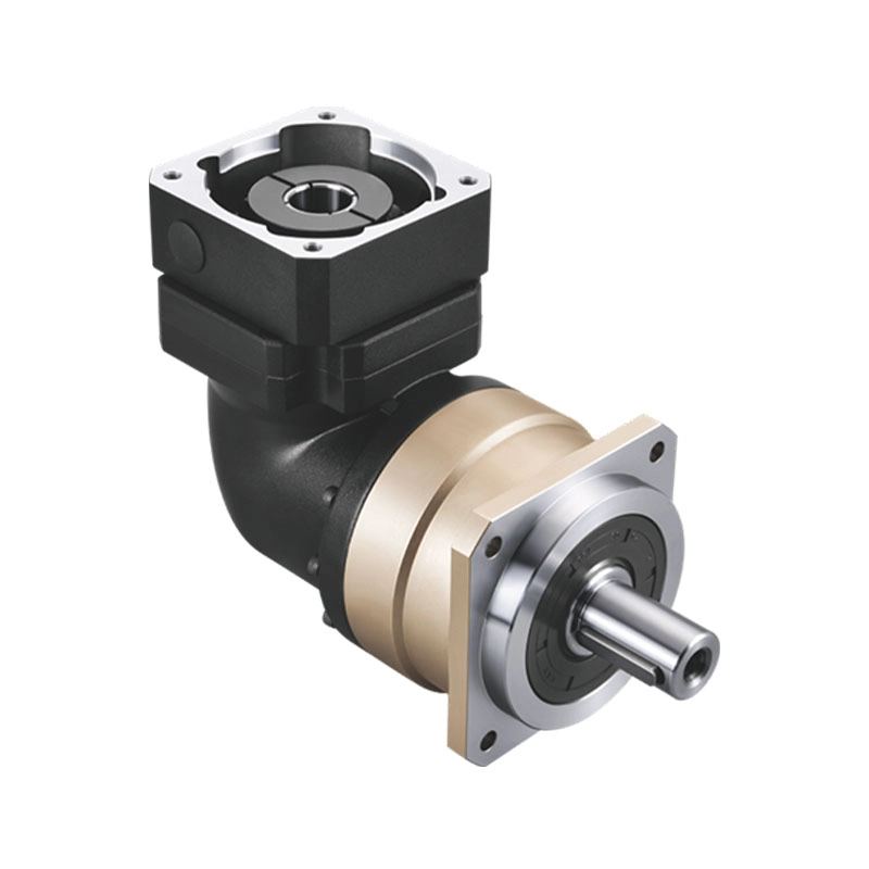
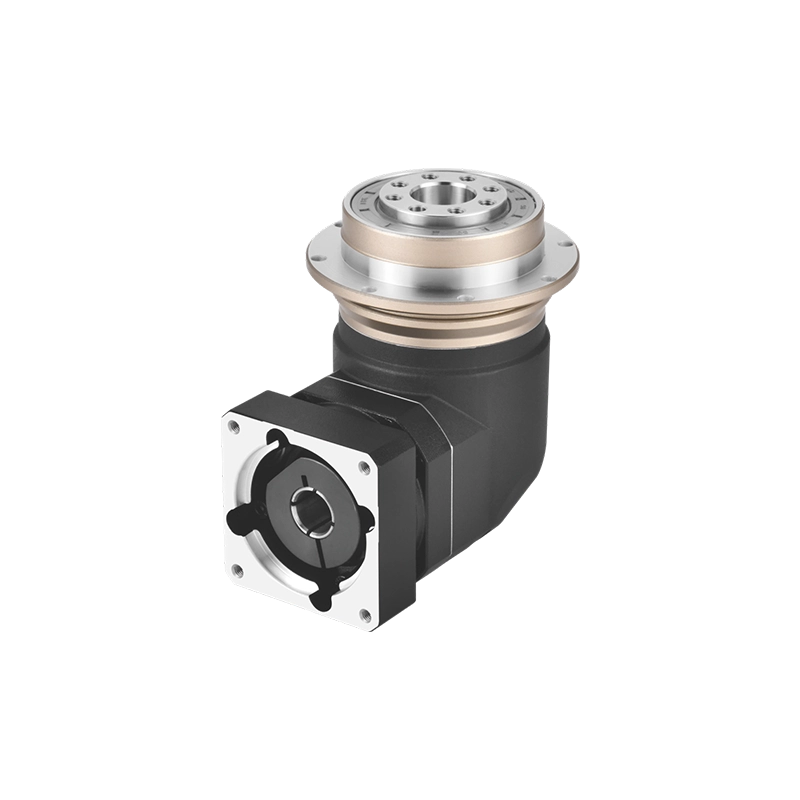
A right-angle reducer allows the motor and output shaft to be arranged at 90 degrees. This is useful when machine space is limited or the motor cannot be installed in line with the driven load.
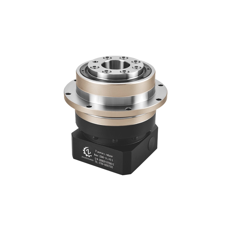
A hollow-output or flange-output reducer may be used when the driven part needs stronger support, direct connection, or a compact rotating structure.
Mounting is not only about convenience. It affects bearing loads, alignment, vibration, installation space, and long-term reliability.
What to Confirm Before Selecting a Speed Reducer
A speed reducer should not be selected only by ratio. Ratio is important, but it is only the starting point.
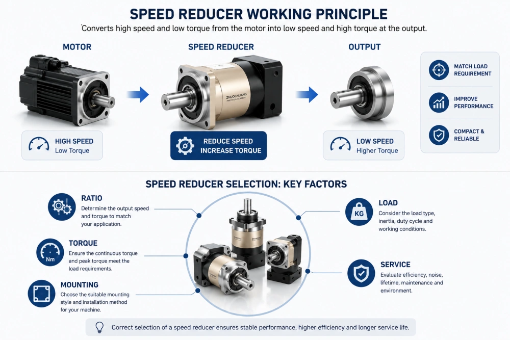
Before choosing a reducer, buyers should confirm the following information.
Motor type and motor model
Input speed
Required output speed
Reduction ratio
Continuous output torque
Peak torque during acceleration or shock load
Load inertia
Backlash requirement
Mounting style
Input and output shaft structure
Duty cycle
Working environment
Ambient temperature
Service life requirement
Quantity and delivery plan
For general industrial machinery, torque capacity, duty cycle, mounting style, and durability are usually the main concerns.
For servo-driven systems, backlash, torsional stiffness, inertia matching, motor adapter accuracy, and repeatability should also be checked carefully.
If the reducer will be used in precision automation, robotics, CNC machinery, or packaging equipment, it is better to send the motor model, machine drawing, or application photo to the supplier before final selection.
Why Two Speed Reducers Can Have Very Different Prices
Speed reducer price can vary widely, even when the ratio looks similar.
A low-cost reducer and a precision reducer may both be called “speed reducers,” but their performance level can be very different.
Gear manufacturing affects price. Ground gears usually cost more than hobbed gears, but they can support smoother meshing and better precision.
Testing affects price. A reducer that is tested unit by unit costs more than one checked only by sampling.
Frame size affects price. Higher torque usually requires larger gears, stronger bearings, and a more rigid housing.
Configuration affects price. A standard inline reducer is usually simpler than a right-angle, multi-stage, flange-output, hollow-output, or customized reducer.
Precision grade affects price. A reducer used for simple transmission does not need the same backlash and stiffness level as one used in servo positioning.
When comparing quotations, buyers should compare reducers with the same ratio, torque rating, precision grade, mounting style, motor interface, and duty cycle. Comparing only the lowest price can lead to poor selection.
Where Speed Reduction Becomes Necessary in Industrial Machines
Speed reducers are used wherever a motor needs to move a machine load at a controlled speed and usable torque.
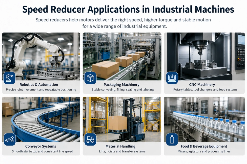
In robotics, reducers help joints move with controlled torque and repeatable positioning.
In automation equipment, reducers support repeated motion in feeding systems, transfer units, indexing mechanisms, assembly machines, and pick-and-place devices.
In CNC machinery, reducers may be used in rotary axes, tool changers, feeding units, and auxiliary drives where stable movement is required.
In packaging machinery, reducers help filling machines, sealing machines, labeling machines, cartoning machines, and conveyors run at controlled speeds.
In semiconductor and precision equipment, reducers may support positioning stages, inspection platforms, wafer handling modules, and transfer systems.
The reducer may not be the most visible part of the machine, but it directly affects motion quality, output force, and reliability.
When a Planetary Reducer Becomes the Better Choice
A speed reducer can be planetary, helical, worm, cycloidal, bevel, shaft-mounted, inline, or right-angle. Each design has its own place.
A planetary reducer becomes especially useful when the application requires compact size, high torque density, servo motor matching, low backlash, and repeatable motion.
This is why planetary reducers are widely used in servo-driven automation, robotics, CNC machinery, packaging equipment, and precision positioning systems.
For applications with large steady loads and enough installation space, helical reducers may be practical. For self-locking or simple right-angle transmission, worm reducers may be suitable. For heavy shock load, cycloidal reducers may be a better choice.
The right reducer depends on the machine problem.
For precision automation projects, Zhuochuang supplies planetary gearboxes in inline and right-angle configurations. If your project requires confirmation of ratio, torque, backlash, mounting style, or motor adapter compatibility, our team can help review the application details before selection.
Browse our planetary gearbox range or contact Zhuochuang for technical support.
FAQ About Speed Reducers
What is a speed reducer?
A speed reducer is a mechanical device that reduces motor speed and increases usable output torque. It helps match motor performance to the speed and force required by the machine load.
What does a speed reducer do?
It converts high motor speed into lower output speed and higher torque. It also helps improve load control, machine layout, and motor sizing.
Is a speed reducer the same as a gearbox?
In many industrial uses, the terms overlap. A speed reducer describes the function, while a gearbox describes the mechanical assembly that contains gears, shafts, bearings, housing, and lubrication.
Why does reducing speed increase torque?
Because the reducer changes the speed-torque relationship. Lower output speed allows higher output torque, minus the losses caused by friction and mechanical efficiency.
Which speed reducer is best for servo automation?
For many servo automation applications, a planetary reducer is often preferred because it offers compact size, low backlash options, high torsional stiffness, and good motor compatibility.
Related Reading
Speed Reducer Gearbox: How It Works and Where It Is Used
Planetary Gear Reducer vs Planetary Gearbox: Meaning, Uses and Buying Tips
How Does a Planetary Gearbox Work?
How to Choose Planetary Gearbox Manufacturers for Industrial Projects