Every machine with a motor and a moving load has a gap between them.
Not a physical gap, but a performance gap.
The motor runs at one speed and torque. The load usually needs another speed and another torque. A conveyor does not need thousands of RPM. A rotary table does not move like a motor shaft. A robot joint does not only need rotation; it needs controlled movement with usable force and repeatability.
Bridging that gap is the job of a gear reducer.
A gear reducer changes the speed and torque relationship between a motor and a load. It allows the motor to run in a suitable operating range while the output side delivers the speed, torque, and control behavior required by the machine.
This article explains gear reducer basics from a practical industrial point of view: what a gear reducer does, how gear ratio is selected, why ratio affects more than speed, how different reducer types fit different machines, and what engineers or buyers should confirm before selecting a reducer.
What a Gear Reducer Does
A gear reducer is a mechanical transmission unit that uses gears to reduce rotational speed and increase output torque.
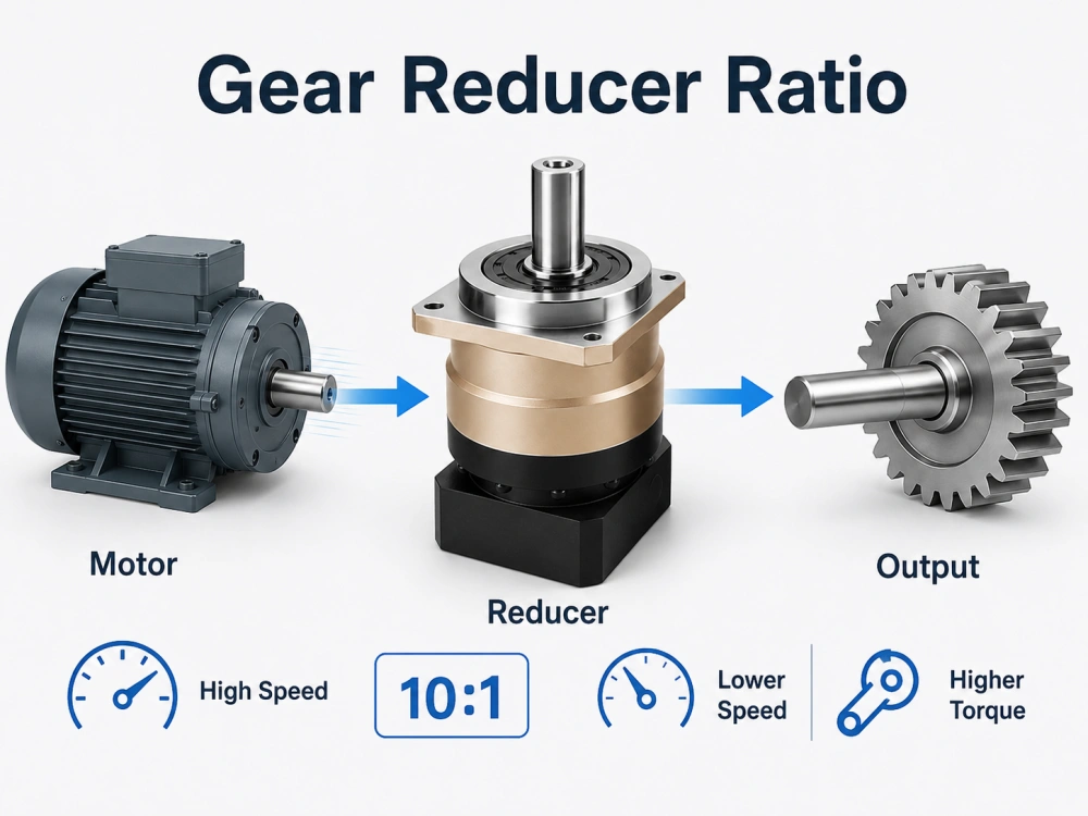
The principle is simple. Gear teeth of different sizes mesh together. When a smaller gear drives a larger gear, the output speed decreases and the output torque increases. The relationship between input speed and output speed is called the gear ratio.
For example, a 10:1 gear reducer takes a 2,000 RPM input and delivers about 200 RPM at the output. In theory, the output torque becomes about 10 times the input torque. In real operation, friction and efficiency losses reduce the final value slightly.
This is why gear reducers are useful. Instead of using a very large motor to produce high torque directly at low speed, a machine can use a smaller motor running at a more efficient speed and then reduce that speed through gears.
The reducer does not create power from nothing. It changes the form of the motor’s power into something the load can use.
In industrial machinery, this usually means:
Lower output speed
Higher usable torque
Better motor-load matching
More compact machine design
Improved motion control
More practical motor sizing
A good gear reducer does more than meet a ratio number. It must also keep gears aligned, support bearings properly, control backlash when required, manage heat, handle duty cycle, and connect correctly to the motor and the driven load.
Gear Ratio: The Number That Starts the Selection
Gear ratio is often the first number in reducer selection.
The basic calculation is:
Motor speed divided by required output speed equals reduction ratio.
If a motor runs at 3,000 RPM and the machine requires 300 RPM at the output, the reducer ratio is about 10:1. If the machine requires 100 RPM, the ratio is about 30:1.
This looks simple, but ratio selection affects more than output speed.
Why Gear Ratio Affects Torque
A higher reduction ratio increases output torque. If the ratio is 10:1, the output torque is approximately 10 times the motor torque, minus efficiency loss. If the ratio is 20:1, the torque multiplication is higher, but the output speed is lower.
This means ratio selection always involves a balance.
If the ratio is too low, the output may not have enough torque.
If the ratio is too high, the output may move too slowly.
If the ratio does not match the machine cycle, the equipment may fail to reach the required working speed.
If the ratio is selected only by torque, the machine may lose productivity.
So the right ratio is not simply the largest ratio. It is the ratio that matches motor speed, output speed, torque demand, acceleration, load inertia, and machine cycle time.
Why Gear Ratio Matters in Servo Systems
In servo-driven machines, gear ratio also affects reflected inertia.
The load inertia seen by the motor is reduced by the square of the gear ratio. This is important because servo motors must accelerate, decelerate, and control the load accurately. A well-selected reducer can make the load easier for the motor to control.
But a ratio that is too high can also create problems. It may reduce output speed too much, make the machine response slower, or create unnecessary stage count and cost.
For servo automation, ratio selection should be considered together with motor sizing, load inertia, required acceleration, backlash, and positioning accuracy.
This is one reason gear reducer selection should happen early in machine design, not after the machine frame and motor have already been fixed.
Single-Stage and Multi-Stage Gear Reducers
A gear reducer may use one gear reduction stage or several stages.
A single-stage reducer is simpler, shorter, and usually more efficient. In many planetary reducers, a single stage commonly covers moderate ratios such as 3:1 to 10:1.
A two-stage reducer provides a higher total ratio by combining two reduction stages. It can reach ratios that a single stage cannot provide, but it becomes longer and may have slightly more efficiency loss and backlash accumulation.
A three-stage reducer provides even higher reduction ratios, but it should only be used when the application truly needs that ratio. More stages can mean more length, more components, more heat, and higher cost.
Before choosing a high ratio, it is worth checking whether the motor speed, output speed, or machine cycle can be adjusted to keep the reducer within a simpler stage arrangement.
A small change in motor speed or output requirement may allow a simpler reducer choice.
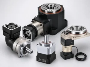
Common Gear Reducer Types
Different gear reducer types exist because machines do not all create the same mechanical problem. Some machines need compact high torque. Some need low cost. Some need a right-angle layout. Some need shock resistance. Some need low backlash for precise positioning.
The reducer type should be selected according to the application, not only according to the catalog name.
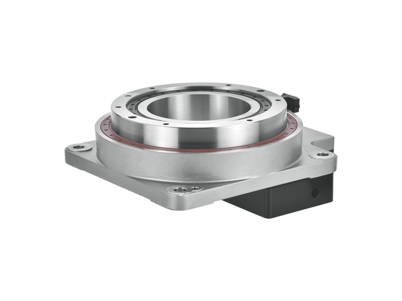
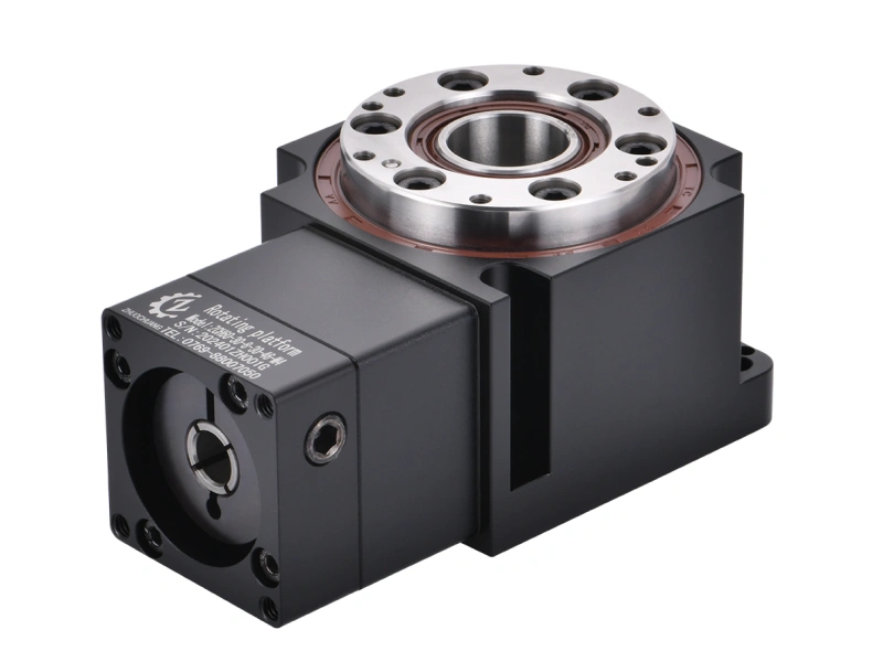
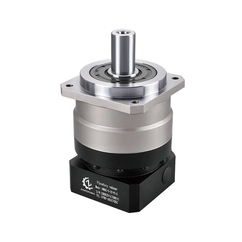
Planetary Gear Reducer
A planetary gear reducer uses a sun gear, planet gears, ring gear, and planet carrier. Several planet gears share the load at the same time, which gives this design high torque density in a compact housing.
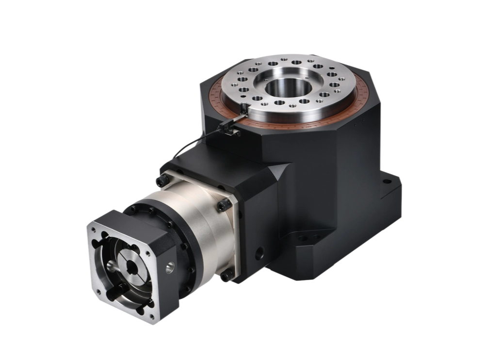
Planetary reducers are commonly used where the machine needs compact size, controlled motion, high torque density, and good compatibility with servo motors.
In servo-driven automation, CNC machinery, robotics, packaging equipment, and precision positioning systems, planetary reducers are often selected because they can support low backlash, high torsional stiffness, and repeatable motion when manufactured to precision grade.
This does not mean planetary reducers are the answer for every industrial machine. For large steady-load machines with enough installation space, other reducer types may be more economical. But when space, precision, and servo control matter, a planetary gear reducer is often the first type to evaluate.
You can view Zhuochuang’s precision planetary gearbox range for automation and motion control applications.
Helical Gear Reducer
A helical gear reducer uses angled gear teeth. Compared with straight spur teeth, helical teeth engage more gradually, which usually reduces noise and vibration.
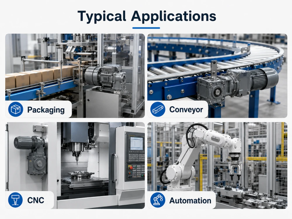
Helical reducers are widely used in general industrial machinery. They are common in conveyors, mixers, processing equipment, and larger power transmission systems where space is available and cost-effective torque transmission is important.
Their offset shaft arrangement can be practical for many machines, but it is not always ideal for compact servo axes where coaxial motor-to-load alignment is preferred.
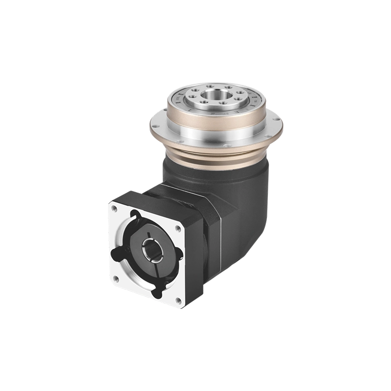
Worm Gear Reducer
A worm gear reducer uses a worm shaft and worm wheel. It can provide a high reduction ratio in a compact right-angle layout.
Worm reducers are often used when the machine needs a 90-degree transmission direction or when resistance to back-driving is useful. Some worm reducers can help hold a load when the motor stops, depending on ratio and design.
The main limitation is efficiency. Worm gear contact involves more sliding friction, which can generate heat and reduce energy efficiency. For high-duty-cycle or precision servo applications, this can be a disadvantage.
Bevel and Hypoid Reducers
Bevel and hypoid gear reducers are used when the drive direction needs to change, commonly by 90 degrees.
Bevel gears use conical gear geometry. Hypoid gears use offset shaft centerlines and can provide different packaging and tooth engagement characteristics.
These designs may appear as standalone right-angle reducers or as part of a combined reducer structure.
They are useful when the machine layout requires the motor and output shaft to be arranged at an angle rather than on the same axis.
Cycloidal Reducer
A cycloidal reducer uses eccentric motion and cycloidal tooth engagement. It can handle high reduction ratios and strong shock loads in a compact structure.
Cycloidal reducers are often used in heavy-duty robot joints, presses, indexing tables, and applications where impact load is severe.
The tradeoff is cost and application fit. A cycloidal reducer can be a strong solution when shock load is the main concern, but it may be more than necessary for many standard automation axes.
Gear Reducer Selection: A Practical Sequence
Selecting a gear reducer should not start with a catalog page. It should start with the machine requirement.
The following sequence is more reliable.
Define the Output Requirement
Start with the output side.
What speed does the load need?
What torque is required during normal operation?
What peak torque occurs during acceleration, braking, or shock load?
What positioning accuracy is needed?
How many hours per day will the machine run?
These details decide the reducer requirement more than the product name does.
Match the Motor and Reducer Together
Motor selection and reducer selection are connected.
Changing the motor speed changes the required ratio. Changing the ratio changes output torque and reflected inertia. For servo systems, these decisions should be made together.
A reducer that looks correct alone may not be correct once motor inertia, load inertia, acceleration, and cycle time are checked.
Calculate the Ratio
Once motor speed and output speed are known, the required ratio can be calculated.
After that, check whether the ratio can be achieved with a standard reducer stage. If the ratio requires multiple stages, confirm whether the additional length, efficiency loss, backlash, and cost are acceptable.
Choose the Reducer Type
Choose the reducer type according to the machine problem.
Use planetary reducers when compact size, servo compatibility, low backlash, and high torque density are important.
Use helical reducers where steady industrial power transmission and cost-effective larger frame sizes are more important.
Use worm reducers where right-angle layout or holding behavior is the main concern.
Use bevel or hypoid reducers when the drive direction needs to change.
Use cycloidal reducers when shock load resistance is especially important.
Specify the Precision Grade
Precision grade matters when the reducer is part of a controlled motion system.
For conveyors, mixers, and many general machines, standard backlash may be acceptable.
For robot joints, CNC axes, indexing systems, and servo positioning applications, backlash can directly affect accuracy and repeatability. In those cases, low-backlash precision reducers should be considered.
Do not over-specify precision if the machine does not need it. But do not under-specify it when positioning accuracy is part of the machine’s function.
Confirm Mounting and Interface
A reducer must physically connect to the motor, machine frame, and load.
Before ordering, confirm:
Motor flange size
Motor shaft diameter
Input adapter requirement
Output shaft or flange type
Mounting direction
Bolt pattern
Available installation space
Load connection method
Many reducer selection problems are not caused by ratio or torque. They happen because the selected unit does not match the motor or machine interface.
Check Duty Cycle and Thermal Rating
A reducer may have enough mechanical torque capacity but still fail because of heat.
Continuous operation, high input speed, high ambient temperature, poor ventilation, or high load can increase thermal stress. For machines that run many hours per day, thermal rating should be checked before final selection.
This is especially important for packaging lines, conveyors, and production equipment that operate continuously.
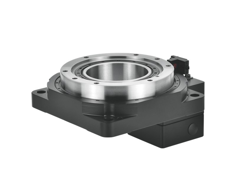
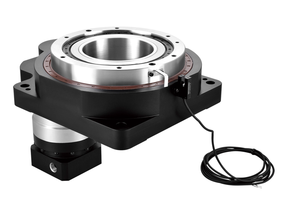
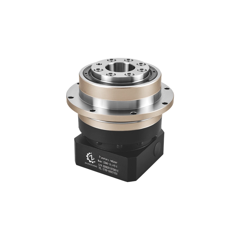
Where Planetary Gear Reducers Fit
Within the gear reducer family, planetary reducers are especially important for servo automation and precision machinery.
They are not simply “better” than every other reducer type. They are better suited to specific requirements:
Compact machine design
High torque density
Servo motor matching
Low backlash options
High torsional stiffness
Repeatable positioning
Coaxial input and output layout
This is why planetary reducers are common in automation equipment, robotics, CNC machinery, packaging machines, and precision positioning devices.
For a conveyor with a large frame and steady load, a helical reducer may be more practical. For a vertical holding application, a worm reducer may be useful. For heavy shock load, a cycloidal reducer may be the better answer.
The right reducer depends on the machine problem.
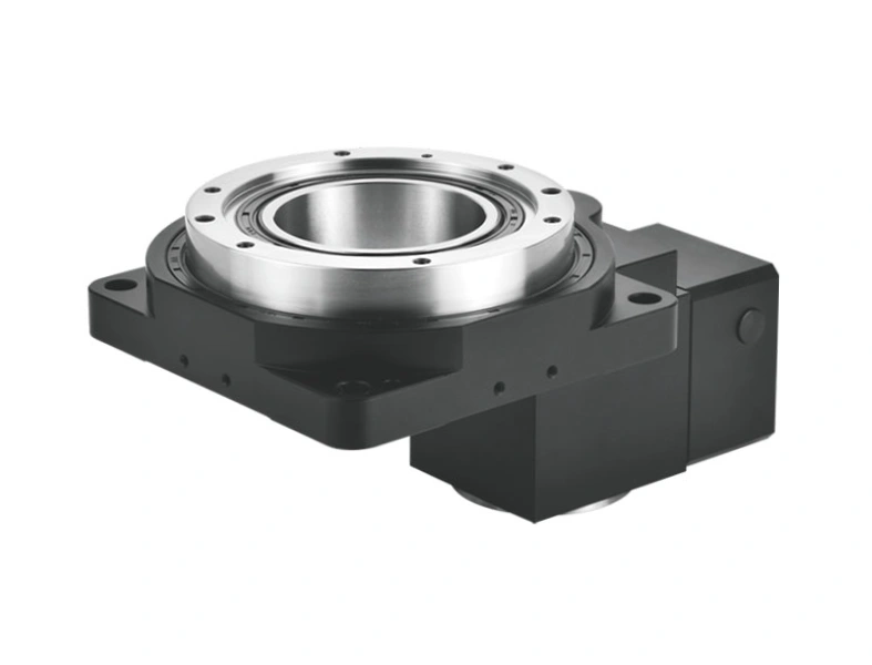
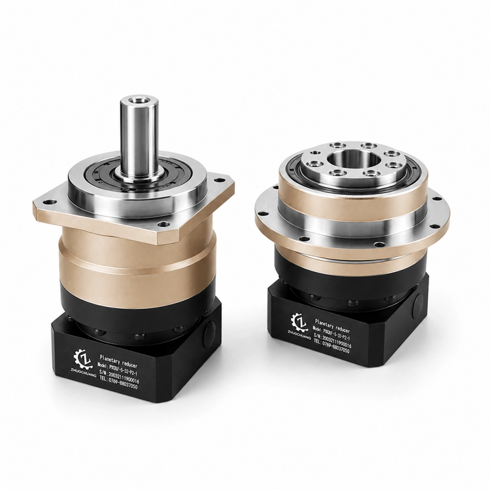
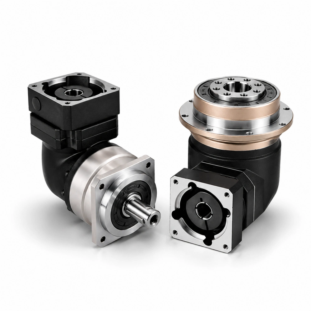
For precision automation projects, Zhuochuang manufactures planetary gear reducers in inline and right-angle configurations. If your project requires ratio, torque, backlash, mounting style, or motor adapter confirmation, our team can help review the application before selection.
Browse our planetary gearbox range or contact Zhuochuang for technical support.
Quality and Documentation Considerations
For industrial buyers, reducer quality is not only about the outside appearance.
A reliable reducer depends on gear machining, heat treatment, bearing selection, housing rigidity, lubrication, sealing, and assembly control. For precision applications, backlash testing and dimensional confirmation also matter.
If the reducer is used in a servo positioning system, it is better to ask whether the supplier can provide clear specifications for backlash, ratio, torque, efficiency, mounting dimensions, and motor adapter compatibility.
For general quality management background, buyers can also refer to ISO as an external source for understanding international standards and quality systems. This does not replace supplier evaluation, but it helps buyers think more clearly about documentation, process control, and consistency.
Common Mistakes When Selecting a Gear Reducer
One common mistake is choosing only by ratio. Ratio matters, but torque, duty cycle, mounting, precision, and thermal rating matter too.
Another mistake is choosing the lowest price without comparing specifications. A standard reducer and a precision reducer may look similar in a quote, but they can perform very differently in a servo machine.
A third mistake is ignoring motor adapter compatibility. If the reducer does not match the motor flange and shaft, installation becomes difficult or may require extra modification.
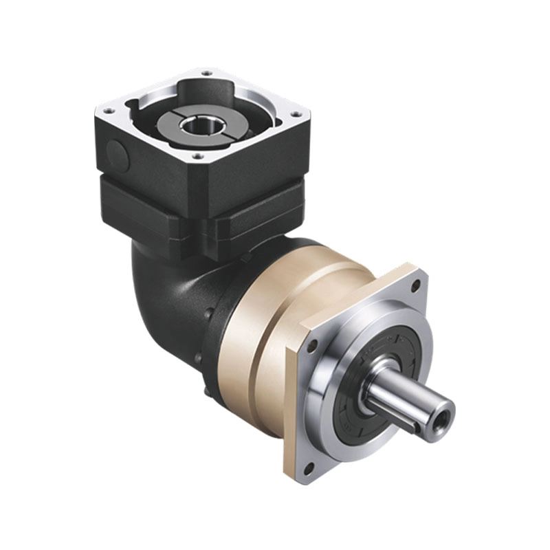
A fourth mistake is using a right-angle reducer only for convenience when an inline reducer would be simpler and more efficient.
A fifth mistake is selecting low backlash when the application does not need it, or selecting standard backlash when the machine actually requires positioning accuracy.
Good reducer selection is not about choosing the most expensive product. It is about matching the reducer to the real operating requirement.
FAQ About Gear Reducers
What is a gear reducer?
A gear reducer is a mechanical transmission unit that reduces motor speed and increases output torque through gear reduction.
Is a gear reducer the same as a gearbox?
In many industrial situations, the terms overlap. A gearbox describes the mechanical assembly, while gear reducer emphasizes the function of reducing speed and increasing torque.
How do I choose a gear reducer ratio?
Start with motor speed and required output speed. Divide motor speed by output speed to estimate the ratio, then check torque, cycle time, load inertia, and reducer stage options.
Which gear reducer is best for servo automation?
For many servo automation applications, a planetary gear reducer is often selected because it offers compact size, low backlash options, high torsional stiffness, and good servo motor compatibility.
Why does reducer precision grade matter?
Precision grade affects backlash, repeatability, and motion accuracy. It is especially important for robot joints, CNC axes, indexing mechanisms, and servo positioning systems.
Related Reading
What Is a Speed Reducer? Industrial Functions, Types and Selection
Speed Reducer Gearbox: How It Works and Where It Is Used
Planetary Gear Reducer vs Planetary Gearbox: Meaning, Uses and Buying Tips
How to Choose Planetary Gearbox Manufacturers for Industrial Projects