
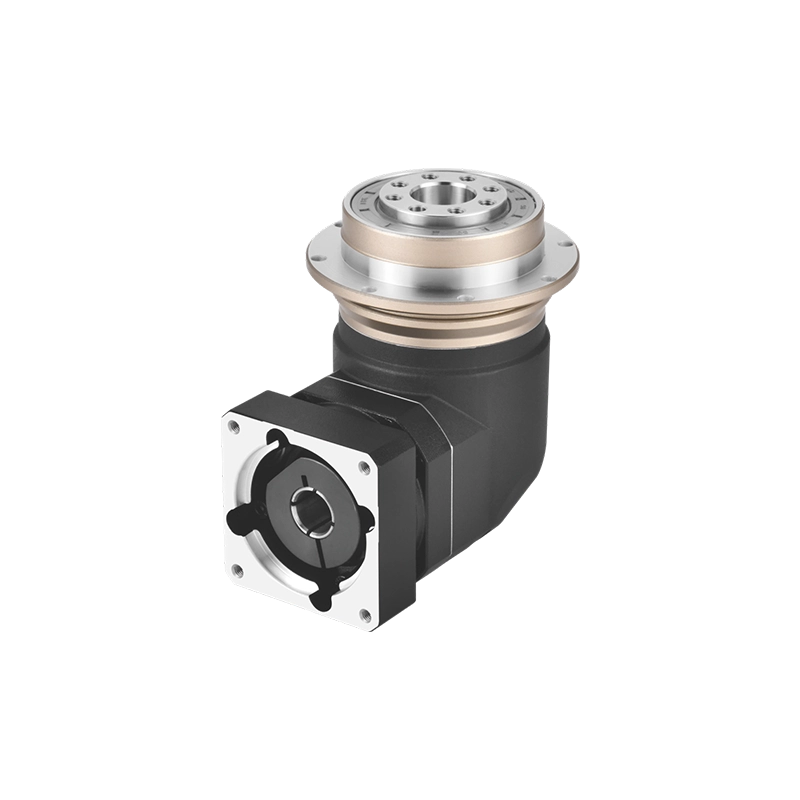
Rotary Positioning Table: A Practical Guide to Precision Positioning in Automation Equipment
When engineers search for a rotary positioning table, they are rarely asking “what is a rotary table.” They already know the shape. What they need to solve is a positioning problem: how to rotate a fixture or workpiece to a specific angle, stop it accurately, hold it under load, and repeat that motion thousands of times without drift. This guide focuses on that problem — angle control, repeatability, fixture design, and motor matching — rather than basic definitions.
A rotary positioning table is the mechanical link between a servo motor’s rotation and a machine’s actual working position. Get that link wrong — undersized torque, excess backlash, poor fixture balance — and the rest of the machine’s accuracy budget is wasted no matter how good the vision system or controller is.
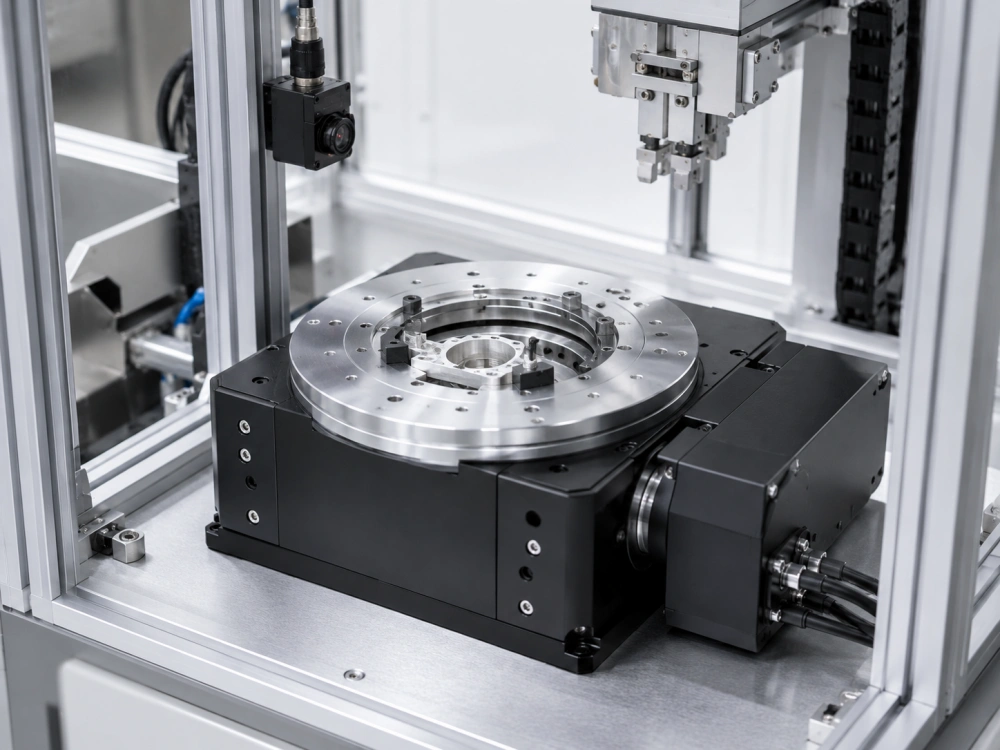
What “Positioning” Actually Means for a Rotary Table
Two tables can share the same diameter and torque rating and still behave very differently once they’re asked to position. The distinction that matters is between indexing (moving to fixed, pre-set stations) and positioning (moving to any commanded angle, often with continuously changing targets set by a PLC or vision system). A rotary positioning table is built for the second case: variable angles, programmable dwell times, and the ability to reverse direction or make small corrective moves without losing accuracy.
In practice, this means the drive train, bearing preload, and servo tuning all need to support fine, repeatable moves in both directions — not just one-way indexing between fixed stops.
Where Precise Angular Positioning Is Actually Used
The applications overlap across industries, but the underlying requirement is the same: hold a part or fixture at a known angle long enough for another process to happen correctly.
- Vision and camera inspection — rotating a part through multiple angles for surface or dimensional checks. (See our dedicated guide on rotary positioning tables for vision inspection equipment for camera-specific setups.)
- Functional and electrical testing — rotating a device under test to bring different connectors, sensors, or probe points into position.
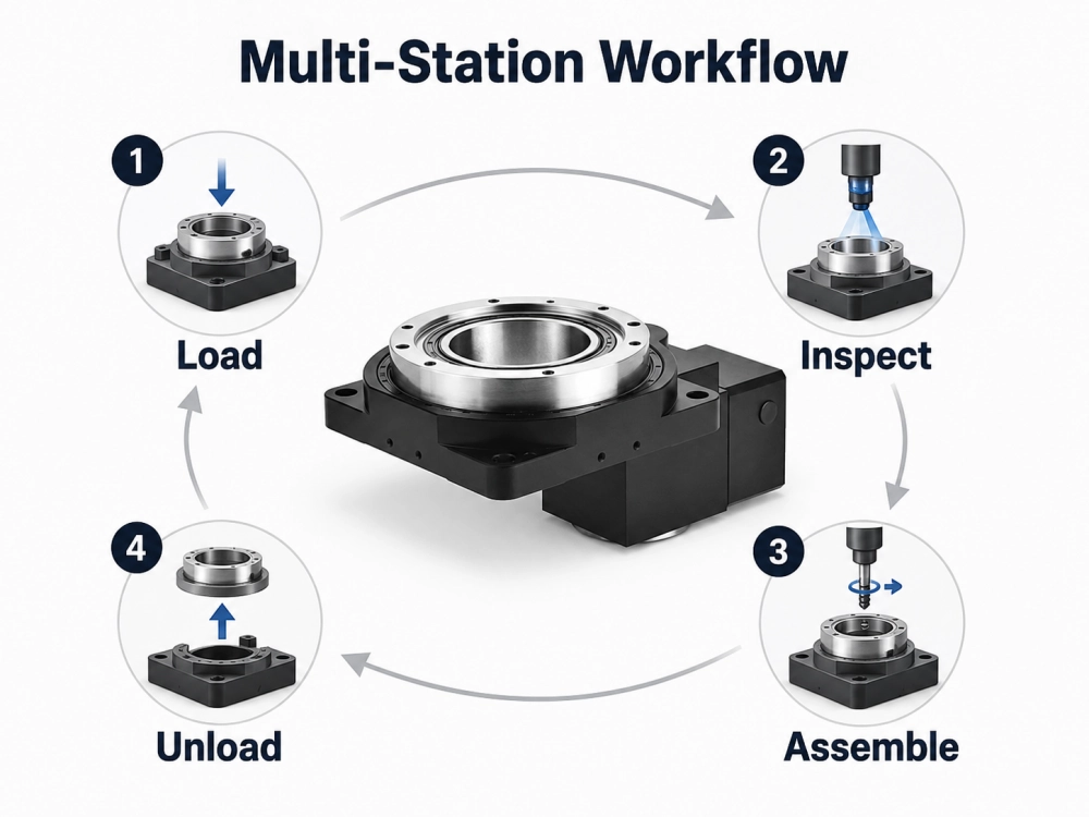
- Multi-station assembly — moving a fixture between load, process, and unload stations with tight repeatability.
- Packaging and labeling — orienting containers for cap alignment, label placement, or code reading.
- Laser marking and dispensing — presenting a fresh face of the part to a fixed tool head.
What differs between these applications isn’t the table itself — it’s the accuracy, load, and cycle-time requirements each process places on it.
The Performance Factors That Actually Decide Positioning Quality
Diameter and torque rating tell you whether a table fits the job. They don’t tell you whether it will position correctly. Four factors do:
Repeatability
How consistently the table returns to the same commanded angle, move after move. This is usually the single most important spec for positioning applications, because a fixture that lands in a slightly different spot each cycle will eventually cause inspection false-rejects or assembly misalignment.
Backlash
Backlash shows up when the table changes direction — the drive has to take up mechanical play before the output actually moves. For applications where the table only ever rotates one way, this matters less. For bidirectional positioning or fine corrective moves, backlash directly limits how precise the system can be.
Load Moment and Rigidity
An off-center fixture, a cantilevered part, or an asymmetric tooling plate creates an overturning moment on the table’s bearing. Undersizing this is one of the most common causes of positioning drift over time — the table itself may be accurate, but the bearing deflects under the actual working load.
Settling Time
The gap between “motion stops” and “position is stable enough to trust.” A table that oscillates briefly after stopping needs a dwell allowance built into the cycle, which affects throughput. Servo tuning, inertia matching, and mechanical stiffness all influence this.
Matching the Servo Motor to a Positioning Table
A rotary positioning table is only half the system — the servo motor and its tuning determine how well that mechanical accuracy translates into real positioning performance. For deeper coverage of servo-driven table selection, see our guide on the servo rotary table for precision positioning. At the sizing stage, three checks matter most:
- Inertia ratio — the reflected load inertia (fixture + workpiece) compared to the motor’s rotor inertia. A poor ratio makes the system harder to tune and more prone to overshoot.
- Torque margin — enough torque not just to move the load, but to accelerate and decelerate it within the cycle time you actually need, with margin for friction and any process load (e.g., a probe pressing against the part).
- Encoder resolution — fine enough to resolve the smallest angular step your process requires, not just the nominal positioning accuracy of the table.
Fixture Design: Where Positioning Accuracy Is Often Lost
It’s common for a well-specified table to underperform simply because the fixture design works against it. A few practical points worth checking before finalizing a design:
- Keep tooling mass centered on the rotation axis where possible; if it can’t be centered, confirm the table’s rated load moment covers the actual offset.
- Route cables, air lines, and sensor wiring through the table’s center bore rather than around the outside — this avoids drag, cable fatigue, and inconsistent resistance that can subtly affect positioning repeatability over thousands of cycles.
- For multi-station layouts, confirm that station spacing accounts for the table’s actual settling behavior, not just its nominal indexing speed.
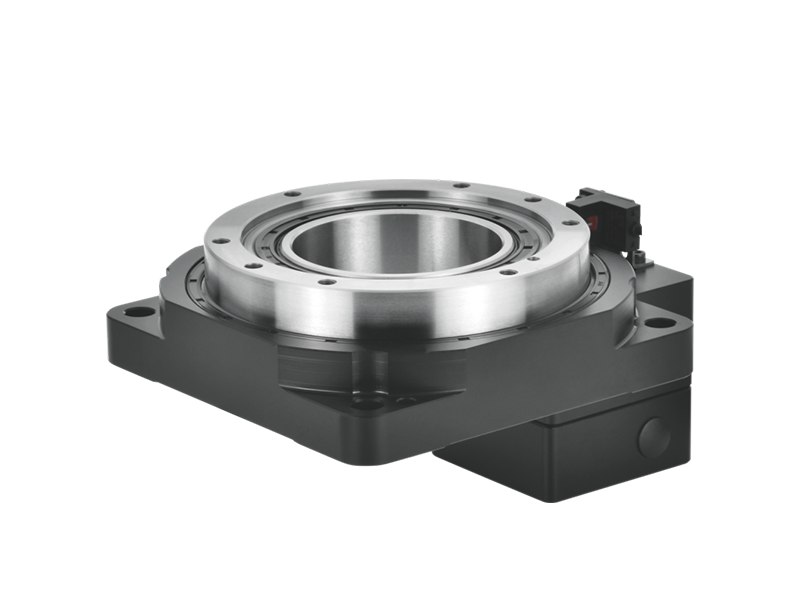
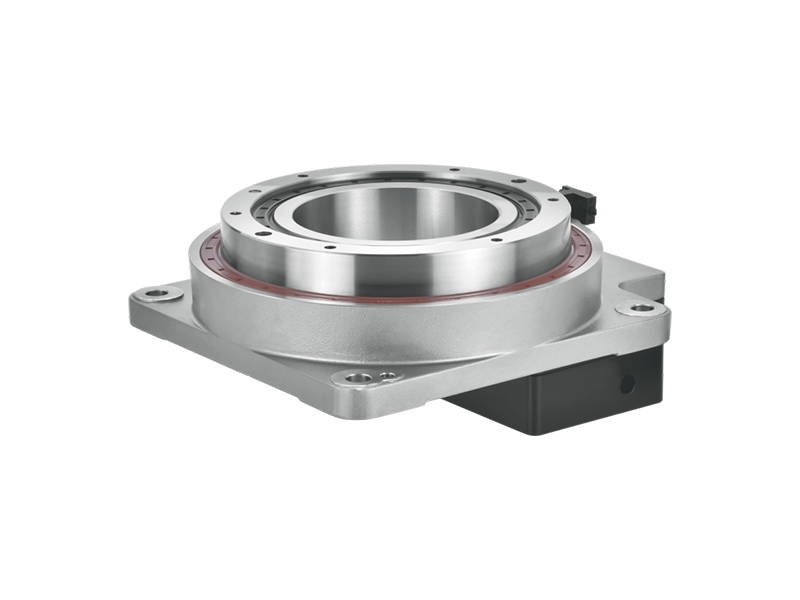
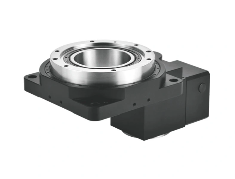
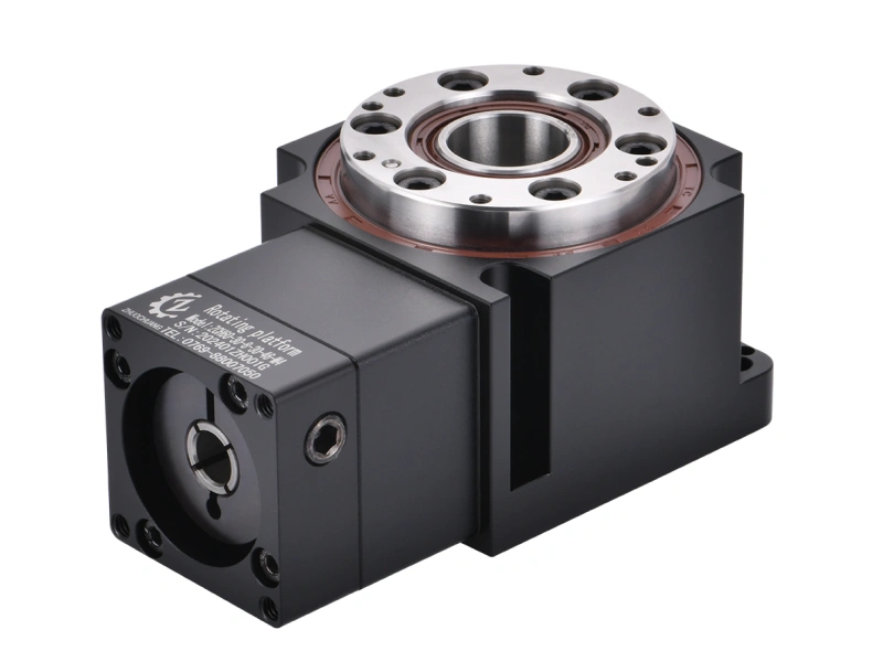
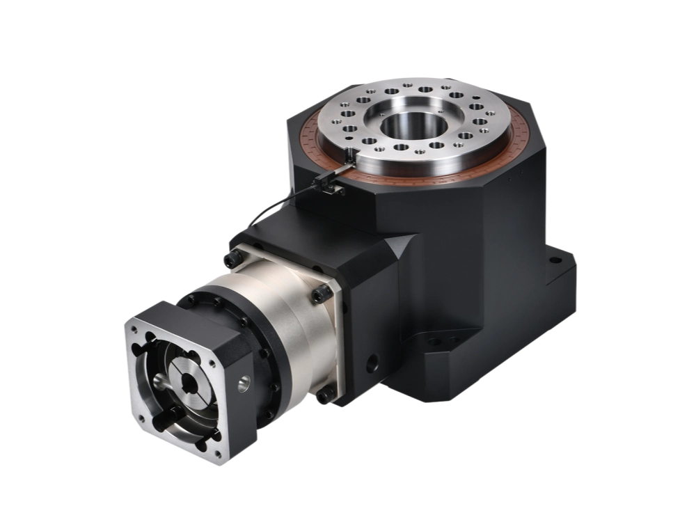
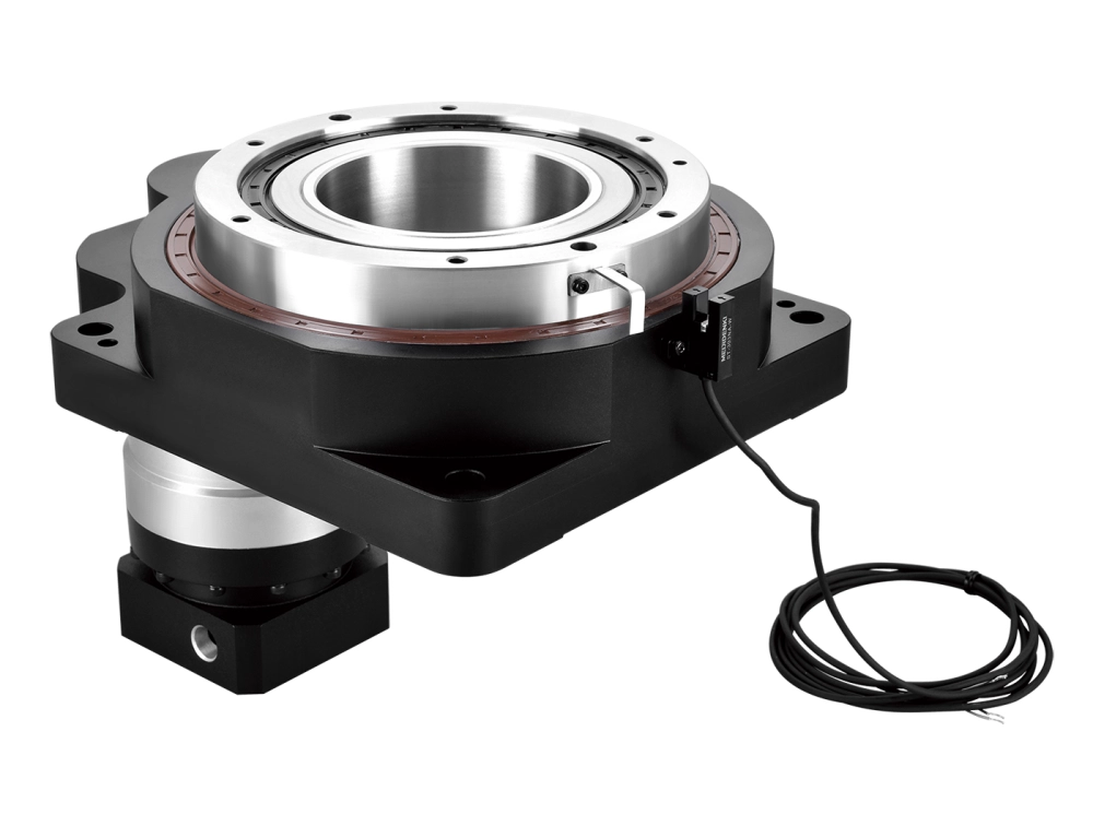
This is also where a hollow-bore design earns its place. Running wiring or pneumatic lines through the center of the rotation axis, instead of around a solid shaft, keeps the fixture footprint compact and avoids cable wrap issues on tables that move back and forth rather than always rotating one direction. Our hollow rotary table product line is built around this structure specifically for positioning-heavy applications; for a broader comparison of when a hollow-bore design is worth the extra cost, see our guide on how to choose a hollow rotary table.
Common Mistakes When Specifying a Positioning Table
- Sizing for the fixture at rest, not in motion. Static load capacity says nothing about acceleration torque or inertia mismatch during a move.
- Ignoring backlash because “it only matters for CNC.” Any bidirectional positioning task — including vision retries or corrective moves — is sensitive to backlash.
- Underestimating cable and wiring drag on long-term repeatability, especially on tables that don’t rotate continuously in one direction.
- Treating positioning accuracy and repeatability as the same spec. A table can repeat consistently while still being off from the theoretical commanded angle — for measurement-critical work, ask for both numbers.
Specifying a Rotary Positioning Table: What to Send Us
Because positioning performance depends on the whole system — table, motor, fixture, and duty cycle — the fastest way to get an accurate recommendation is to share the actual application data rather than a target model number. Useful information includes:
- Fixture and workpiece weight, plus their approximate center of mass relative to the rotation axis
- Required angular steps or positioning pattern (fixed stations vs. fully variable angles)
- Cycle time and required settling time
- Repeatability and accuracy tolerance
- Bore requirement, if wiring or air lines need to pass through center
- Preferred motor interface or existing servo motor model
Send this to our engineering team through the contact page and we’ll help match a table and drive configuration to the actual duty cycle rather than a generic spec sheet.
FAQ
What is the difference between a rotary positioning table and a rotary indexing table?
An indexing table is optimized for moving between a fixed set of stations, often in one direction. A rotary positioning table is built to move to variable, programmable angles in either direction, which typically requires tighter backlash control and more careful servo tuning.
How accurate is a typical rotary positioning table?
It depends heavily on the drive type, bearing preload, and load condition, so published accuracy figures should always be read alongside the rated load and moment they were measured under. Repeatability and positioning accuracy should be requested as separate numbers for applications where both matter.
Do I need a hollow-bore rotary positioning table?
If your fixture needs wiring, pneumatic lines, or sensor cables running through the rotation axis — or if the table moves back and forth rather than always in one direction — a hollow-bore design generally simplifies cable management and improves long-term reliability compared to routing cables externally.
What torque margin should I use when sizing the servo motor?
A common starting point is enough margin to cover acceleration torque, friction, and any process load (such as a test probe or fixture clamp) with headroom left over — but the correct margin depends on your specific inertia ratio and cycle time, which is why sharing application data gets a more reliable recommendation than a generic rule of thumb.
Can an existing servo motor be reused with a new rotary positioning table?
Often yes, provided the motor’s torque, speed, and inertia characteristics are compatible with the new table’s reflected load and the motor interface (flange and shaft) can be matched or adapted. Sharing the current motor model with our team lets us confirm compatibility during model selection.