
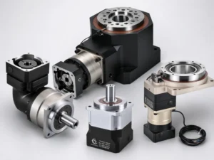
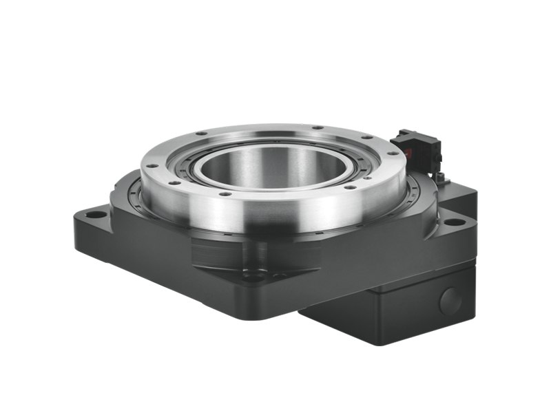
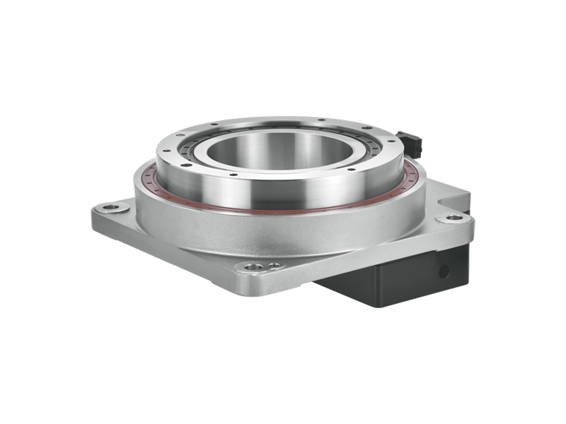
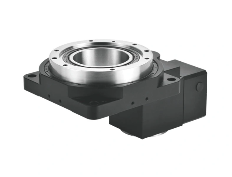
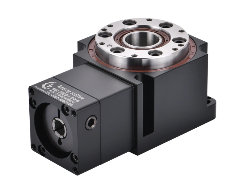
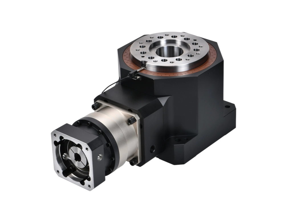
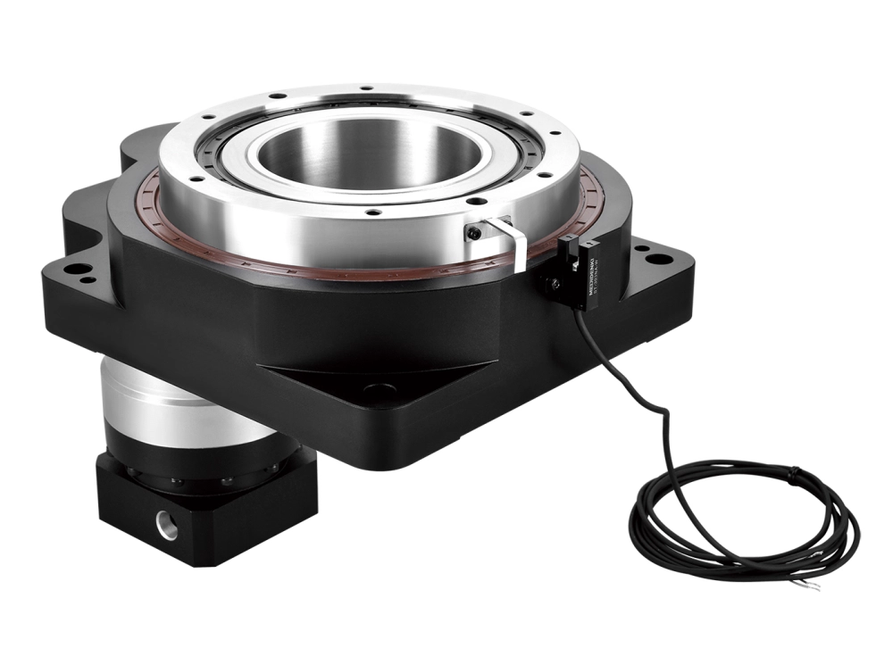
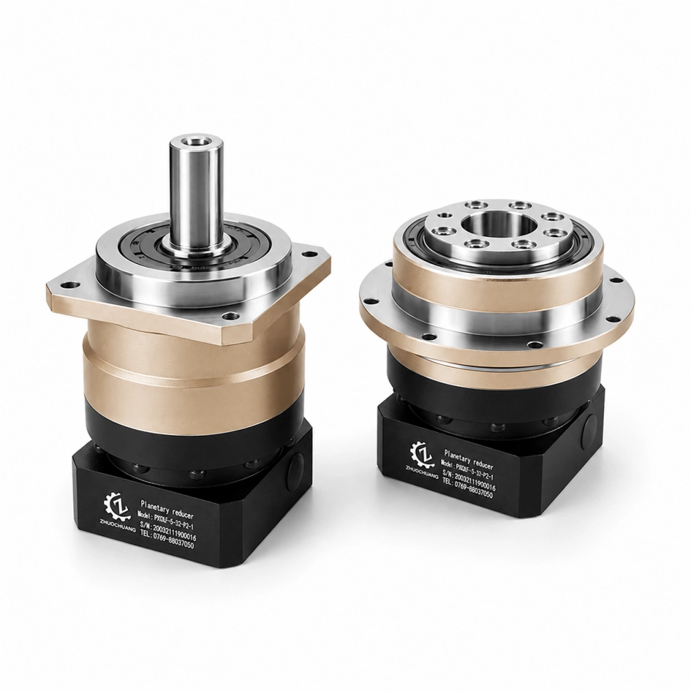
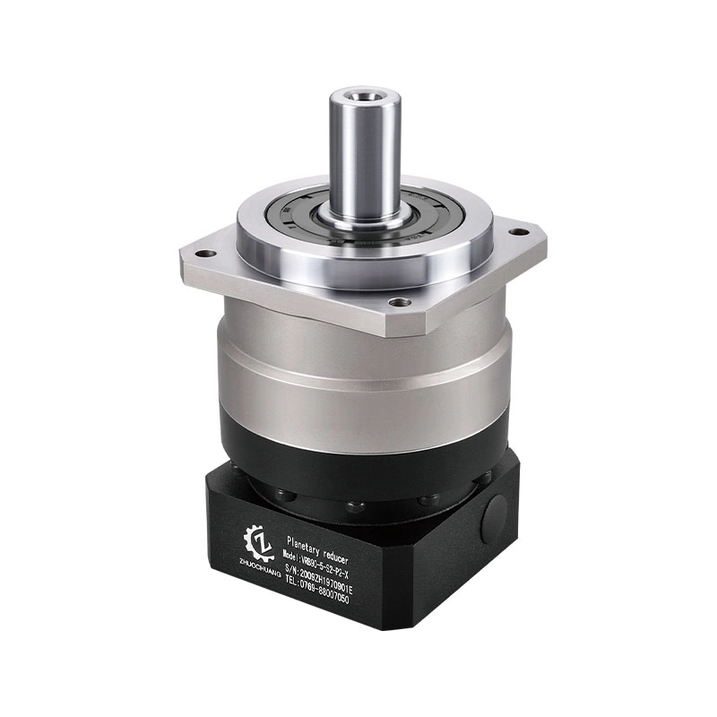
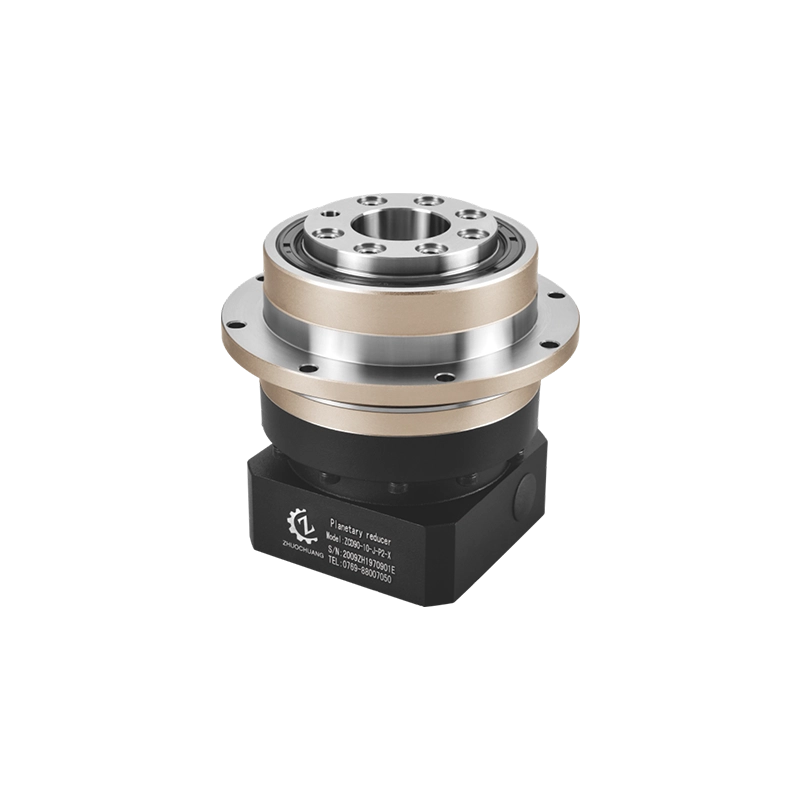
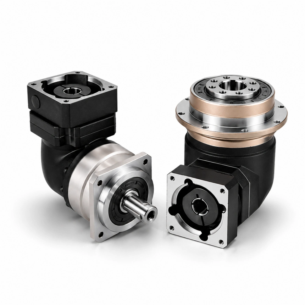
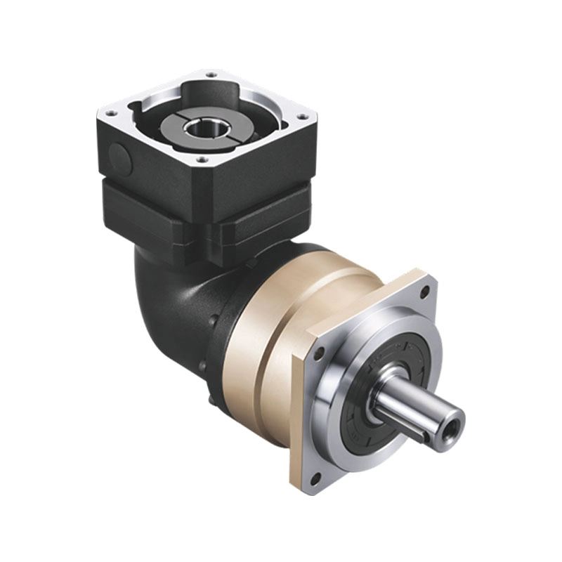
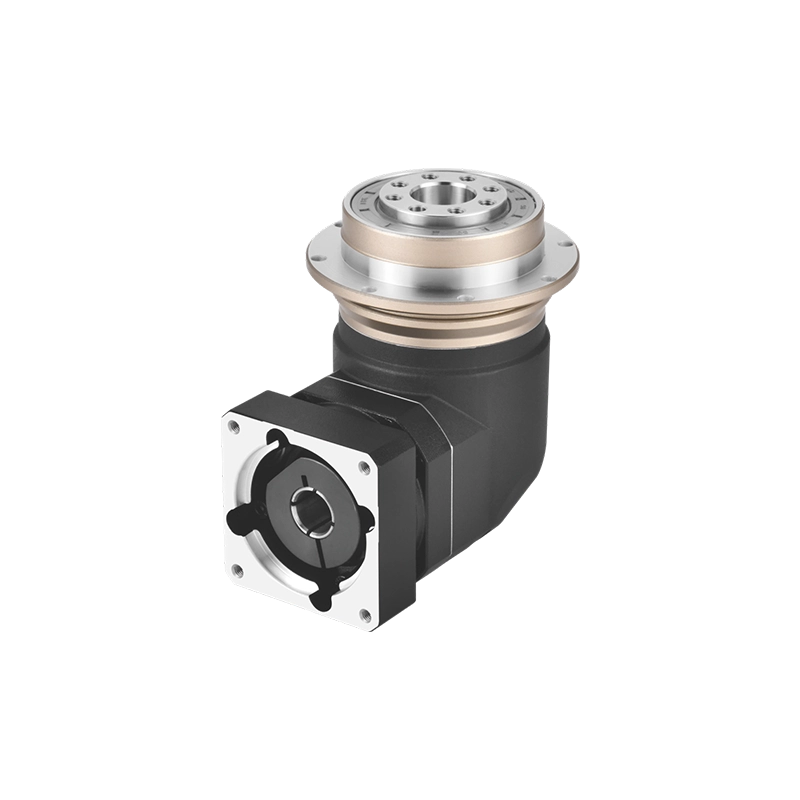
A machine drawing may show a motor turning power through 90 degrees, but that alone does not specify a bevel gear reducer. The first question is geometric: do the input and output shaft centerlines intersect, or are they offset? The next questions concern rotation direction, shaft position, external load, allowable backlash and motion profile. These details determine whether a conventional bevel drive, another right-angle reducer, or a precision right-angle planetary gearbox is the better fit.
Quick answer: a bevel arrangement is a practical starting point when intersecting shafts and a change in power direction define the machine layout. A precision right-angle planetary solution deserves closer consideration when the axis must reverse frequently, stop repeatably, integrate with a servo motor or operate within a tightly controlled backlash requirement. Neither choice should be approved from the words “90 degree gearbox” alone.
Read the Machine Drawing Before Selecting a Bevel Gear Reducer
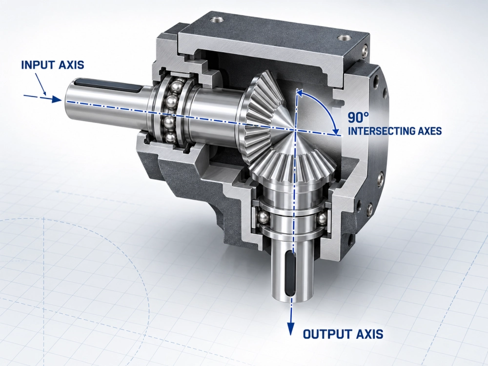
A useful selection discussion begins with two centerlines drawn through the input and output shafts. In a conventional bevel pair, the shaft axes intersect, commonly at 90 degrees. A hypoid arrangement also changes direction, but its shaft axes are offset rather than intersecting. Worm, parallel-shaft and right-angle planetary designs create still other power paths. Treating all of them as interchangeable right-angle gearboxes hides important differences in mounting, efficiency, backlash and bearing loads.
1. Mark the input and output centerlines
Do not judge the relationship from the housing shape. Extend both shaft centerlines on the machine drawing. If they meet, a bevel gear set may suit the geometry. If they remain separated, the application needs an offset architecture. Also record the angle if it is not exactly 90 degrees; special shaft angles require a model designed for that geometry rather than an improvised mounting arrangement.
2. Confirm which side is input and which side is output
Catalog pictures can be rotated, and a housing that appears to fit may put the output on the wrong side. Mark the motor location, driven-machine location and required output rotation when viewed from a stated end. A single bevel mesh changes the spatial direction of rotation, but the observed clockwise or counterclockwise result depends on viewing direction and gear arrangement. A sketch with arrows is safer than a verbal instruction.
3. Locate the mounting face and the applied load
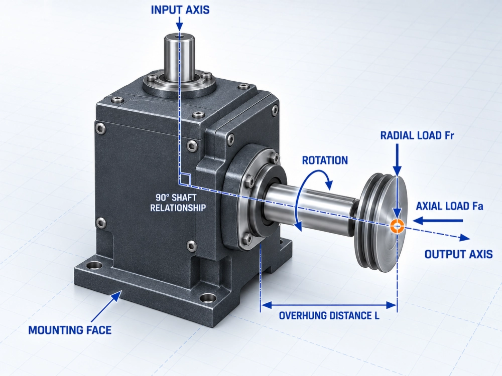
Show the machine mounting surface, shaft extension, coupling or pulley, and the distance from the bearing support to the load center. A compact body does not guarantee that the output bearing can carry an overhung sprocket, belt tension or cantilevered arm. If the driven component mounts directly to a flange, provide its bolt circle, pilot, register depth and load position as well.
4. Separate direction change from speed reduction
A bevel gear set can change direction and provide a ratio, but a complete bevel gear reducer may contain additional reduction stages. Ask for the total gearbox ratio and the individual architecture rather than assuming that the visible bevel pair provides all reduction. The required ratio should come from rated motor speed and desired machine speed, then be checked against an available catalog ratio.
Drawing rule: if a supplier cannot identify the shaft relationship, mounting face, output direction and load position from the information supplied, the gearbox is not ready for approval.
What the Bevel Tooth Form Changes—and What It Does Not
The words “bevel gear” describe a family, not one universal performance level. Straight bevel teeth are comparatively simple and can be suitable for moderate speeds and straightforward duties. Spiral bevel teeth engage more gradually, which can support smoother running in appropriately designed higher-speed or higher-load systems. Actual noise, efficiency and capacity still depend on tooth geometry, accuracy, material, heat treatment, lubrication, bearing support and assembly quality.
A spiral bevel gear reducer also requires careful control of thrust and mounting accuracy. Spiral tooth contact generates force components whose magnitude and direction change with hand of spiral, driving member and rotation. The phrase “spiral bevel” therefore does not remove the need for model-specific bearing and load data. Buyers comparing precision right angle bevel gear reducers should request measurable backlash, stiffness, runout and speed limits instead of relying on the word “precision.”
Do not use tooth form as a substitute for a motion specification. A bevel reducer can be accurately manufactured, but “precision” must still be expressed through allowable backlash, repeatability, torsional stiffness, runout and the actual torque at which those values matter. Likewise, a high input-speed claim must be supported by the model’s rated speed, lubrication method, thermal limits and duty cycle.
Follow the Gear Forces into the Bearings
Torque is only part of the selection. Bevel tooth contact produces tangential force for torque transmission plus radial and axial components. Those forces pass through the shafts into the bearings and housing. External belt pull, sprocket load, pinion force or a cantilevered fixture adds another load system at the output.
For a meaningful bearing check, provide continuous torque, acceleration and deceleration torque, emergency-stop torque, output speed, radial force, axial force and the distance from the gearbox face to the load center. The manufacturer can then compare the combined condition with the permitted radial load, axial load and moment for the exact model. Shaft diameter alone is not a bearing-capacity rating.
Thermal duty matters too. A gearbox running a conveyor continuously has a different heat balance from one indexing for two seconds and resting for eight. State operating time, starts per hour, ambient temperature and enclosure conditions. Oil or grease choice, fill quantity and mounting orientation can affect lubrication of the mesh and bearings, so the approved orientation should appear on the final drawing.
Right-Angle Selection Map
This table is a screening tool, not a substitute for catalog ratings. Use the strongest evidence in the machine requirement, then ask suppliers for model-specific confirmation.
| Evidence from the machine | Direction for a bevel reducer | Direction for a right-angle planetary gearbox |
|---|---|---|
| Intersecting input and output axes define the layout | Natural architecture to evaluate | Confirm the product’s internal right-angle input and output interface |
| Steady rotation with moderate positioning demands | Often a practical candidate when ratings fit | Possible, but precision features may be unnecessary |
| Frequent reversing, indexing or registration | Require quantified backlash and stiffness data | Often the stronger candidate for servo control |
| High ratio in a compact servo package | May require a bevel stage plus other reduction stages | Evaluate available ratios, inertia and overall length |
| Large overhung or tilting load | Compare the exact output-bearing rating and load position; housing appearance is not evidence | |
| Motor must turn 90 degrees in limited axial space | Check adapter and coupling requirements | Review a purpose-built right-angle planetary gearbox and its servo interface |
Three Machines, Three Different Answers
Cross-transfer conveyor: layout and duty lead the decision
Consider a conveyor whose motor must sit beside the frame while the driven shaft runs across it. The machine needs continuous rotation, predictable service life and convenient mounting, but not arc-minute positioning. A conventional right angle gear reducer using bevel gearing may be a sensible candidate if its ratio, service factor, thermal capacity and shaft loads are verified. In this case, paying for very low backlash may add little operational value.
The buyer should pay more attention to belt or chain pull, overhung distance, operating hours, contamination and access for lubrication. The best quote is the one that answers those conditions, not simply the lowest nominal power rating.
Packaging registration axis: motion quality changes the answer
A registration axis may accelerate, stop at a defined position, reverse during correction and repeat that cycle thousands of times. Here, average torque hides the most demanding events. The specification needs peak torque duration, load inertia, allowable backlash, repeatability and torsional stiffness. Motor-shaft fit and reflected inertia also affect tuning.
A bevel stage may still be part of the solution, but the selection is no longer just “which bevel gear reducer fits the space?” A purpose-built precision right-angle planetary gearbox may provide a more coherent servo interface and controlled motion specification. Compare complete model data rather than assuming that either architecture is automatically superior.
Robot auxiliary axis: bearing moment can be the hidden limit
A compact robot positioner or auxiliary axis may place a tooling plate away from the output face. The resulting tilting moment can govern selection before motor power or ratio does. The engineering drawing should show the center of mass, offset distance, acceleration direction and emergency-stop case. If an external bearing supports the load, show that support explicitly; otherwise the gearbox supplier may assume the reducer carries forces that the machine designer intended to isolate.
For this application, compare allowable moment, bearing arrangement, backlash under load, stiffness and mounting accuracy. A smaller body is useful only if it survives the actual load path and maintains the required position.
Drawing and RFQ Check List
Send one annotated machine sketch and the following data for bevel gear reducer selection. This shortens selection time and makes quotations easier to compare:
- Motor brand, complete model number, rated speed, maximum speed and shaft dimensions;
- Input and output centerlines, required shaft angle and whether they intersect or are offset;
- Required output direction, with clockwise or counterclockwise defined from a named viewing end;
- Desired output speed or total reduction ratio;
- Continuous torque, acceleration torque, deceleration torque, peak duration and emergency-stop torque;
- Load inertia, acceleration time, cycle time, starts per hour and daily operating hours;
- Required backlash, repeatability and stiffness where positioning matters;
- Radial force, axial force, overhung distance and tilting moment at the output;
- Mounting face, pilot, bolt pattern, shaft extension, coupling and available installation envelope;
- Ambient temperature, dust, moisture, washdown and mounting orientation;
- Requested drawing or CAD format, quantity and target delivery schedule.
A supplier may request additional details after reviewing the duty. That is a positive engineering step: the purpose of the list is to expose the conditions that a short request such as “need a 10:1 bevel gearbox” leaves unanswered.
Related Reading
- 90 Degree Gear Reducer — a broad map of worm, bevel, hypoid and planetary right-angle architectures.
- Right Angle Planetary Gearbox — structure, layouts and selection within the planetary category.
- Right Angle Servo Gearbox — motor integration, motion duty and positioning requirements.
- Types of Gear Reducers — a wider comparison of reducer families and their selection logic.
Technical Reference
The ISO 10300 series addresses calculation of load capacity for bevel gears. It is a design and rating reference, not a replacement for the manufacturer’s limits for a complete assembled gearbox. Final approval should use current data for the exact model, lubrication, mounting position and application duty.
Approve the Power Path, Not Just the Product Name
The correct bevel gear reducer is the one whose shaft geometry matches the drawing and whose gears, bearings, housing, lubrication and interfaces carry the real duty. Begin with intersecting versus offset axes, then verify rotation, total ratio, torque cycle, thrust, external loads, backlash and mounting. If servo positioning or frequent reversal changes the priorities, compare a precision right-angle planetary solution using the same operating data.