
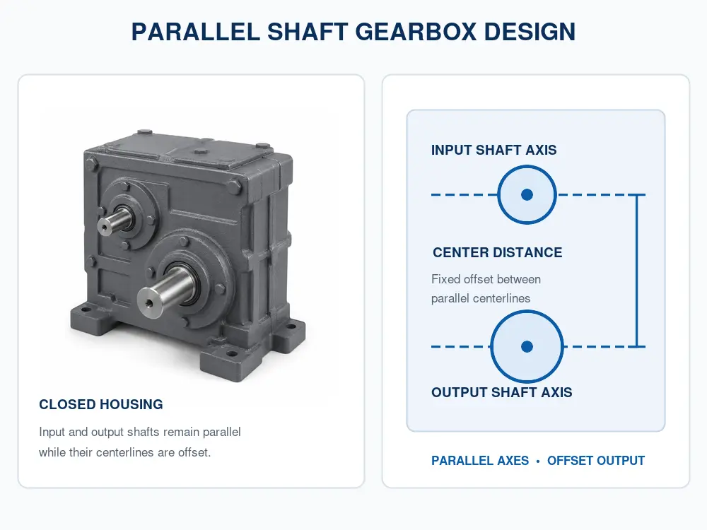
A parallel shaft gearbox design begins with geometry rather than a product name. The input and output shafts point in the same direction, but their centerlines are separated by a fixed distance. Gear pairs bridge that distance, moving power from one shaft to another while changing speed and torque. The housing, bearings, lubrication system and mounting arrangement must then keep those gears aligned under load.
This guide follows the power path through the gearbox instead of comparing product catalogs. It explains why center distance controls the package, how spur and helical teeth behave, what changes when another stage is added, and why a gearbox drawing must show more than an outside envelope.
In one sentence: a parallel shaft gearbox uses gears on parallel, offset shafts; its final performance depends on tooth geometry, shaft stiffness, bearing support, housing accuracy, lubrication and the real operating duty.
The Drawing Starts With Center Distance
Place two gears in mesh and draw a line between their rotational centers. That dimension is the center distance. In a basic parallel shaft gearbox design, it establishes the offset between the input and output shafts and strongly influences gear diameter, housing size, bearing locations and the space needed around the shafts.
Center distance is not an arbitrary packaging number. For a selected tooth system, it is related to the pitch diameters of the mating gears. A larger driven gear can create a higher reduction ratio for that stage, but it also requires more space. Trying to force a very high ratio into one small stage may lead to impractical gear proportions, inadequate tooth strength or an unacceptable center distance.
The designer therefore works with several connected variables:
- Required ratio and output speed;
- Gear tooth count and pitch diameter;
- Module or diametral pitch;
- Pressure angle and tooth form;
- Face width and allowable tooth load;
- Shaft diameter and bearing span;
- Housing wall thickness and mounting envelope.
Changing one variable can move several others. This is why two parallel gearboxes with the same nominal ratio may have different dimensions, torque ratings, noise levels and service limits.
Follow the Power Path Through One Gear Mesh
The simplest parallel gear drive contains a smaller driving gear and a larger driven gear. The motor rotates the input shaft. The input gear applies tangential force at the tooth contact, and the mating gear transfers that force to the output shaft. Output speed falls in proportion to the tooth-count relationship, while available output torque rises subject to mechanical efficiency and the gearbox rating. This one-mesh power path is the foundation of a basic parallel shaft gearbox design.
For a single external gear pair, the two shafts rotate in opposite directions. Additional external meshes can change the final direction again. That detail matters when a machine must preserve a required output rotation, but it should be confirmed from the complete transmission arrangement rather than guessed from the housing.
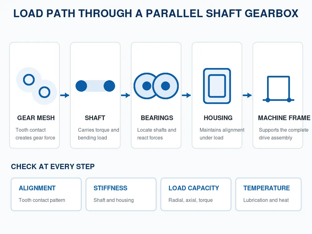
The visible output shaft is only the final part of the load path. Torque travels through the tooth contact, gear hub, key or spline where used, shaft shoulders, bearings and housing before reaching the machine frame. A sound parallel shaft gearbox design treats this as one connected structural system.
Spur and Helical Teeth Change the Behavior
A parallel shaft spur gear gearbox uses teeth that run parallel to the shaft axis. Spur gears are conceptually simple and do not generate the same axial thrust associated with a helical mesh. Depending on speed, tooth accuracy and load, however, tooth engagement can produce more noticeable noise and vibration.
Helical teeth are inclined relative to the shaft axis. Their engagement develops progressively across the face width, which can support smoother and quieter running. The tradeoff is axial force. Bearings, shoulders and housing features must be arranged to react that thrust in addition to radial gear forces.
The word “helical” does not by itself guarantee quiet operation or high capacity. Tooth accuracy, surface finish, contact pattern, alignment, lubrication, pitch-line velocity and housing stiffness all contribute. Likewise, a spur gearbox is not automatically unsuitable for industrial service. The correct tooth form follows the speed, load, noise target, manufacturing method and cost constraints.
What Another Reduction Stage Changes
If one gear mesh cannot provide the required ratio within practical tooth counts and dimensions, the parallel shaft gearbox design may add an intermediate shaft. Power then passes from the input shaft to the intermediate shaft and from the intermediate shaft to the output shaft. The total ratio is the product of the individual stage ratios.
Adding a stage can make a higher total ratio practical, but it changes more than speed:
- The housing must accommodate another shaft and gear pair;
- More bearings and seals are required;
- Rotating inertia, friction and heat can increase;
- Every mesh contributes to the complete backlash and efficiency;
- The lubricant must reach all loaded tooth contacts and bearings;
- Assembly tolerances must maintain alignment across more components.
This article explains how the shaft map changes; our separate guide to a double reduction gearbox covers ratio multiplication, efficiency and the decision to use two consecutive reduction stages.
Gear Teeth Cannot Stay Aligned Without Structural Support
Gear calculations alone do not define a reliable parallel shaft gearbox design. Each shaft deflects under transmitted torque and gear forces. Bearings also move by small amounts under load, and the housing changes shape with load and temperature. If the combined displacement is excessive, the tooth contact pattern can move toward an edge rather than remain distributed across the intended face width.
Shaft stiffness
Shaft diameter, unsupported length, shoulder geometry and gear position affect bending and torsional deflection. Placing a gear far outside the bearing span can create a substantial overhung load. Keeping the gear close to its supporting bearings generally improves stiffness, although assembly and lubrication requirements still influence the final arrangement.
Bearing arrangement
Bearings locate the shafts, carry radial gear forces and, in helical arrangements, react axial thrust. The design must establish which bearing locates the shaft axially, how thermal expansion is accommodated and how preload or internal clearance affects running. Bearing capacity should be evaluated with the actual force direction and duty, not only a catalog radial rating.
Housing accuracy
The bearing bores in a parallel shaft reducer gearbox must hold the intended center distance and alignment. A stiff-looking casting can still perform poorly if the bores are inaccurate, the joint faces move or the mounting feet distort the case when bolted down. The housing is part of the gear alignment system, not merely a cover.
Lubrication, Heat and Mounting Position Belong in the Design
Lubricant separates contacting surfaces, reduces wear, carries heat and protects components. The required method may be splash lubrication, grease, forced circulation or another engineered system, depending on speed, load, orientation and gearbox size.
Mounting position changes where oil collects. A level suitable for one orientation may leave an upper bearing or gear inadequately supplied in another, while too much oil can increase churning losses and heat. Oil fill, drain, level and breather positions therefore need to match the approved installation orientation shown for that parallel shaft gearbox design.
Seals must retain lubricant while accommodating shaft speed, surface condition, temperature and contamination. A shaft-mounted fan, coupling, pulley or sprocket can also affect airflow and seal access. These details explain why a catalog image cannot confirm that a parallel shaft speed reducer is suitable for every mounting direction.
Thermal capacity can limit continuous operation even when the gears can withstand the calculated torque. Losses from tooth contact, bearings, seals and lubricant become heat that must leave through the housing and surrounding air or an auxiliary cooling system.
Read the Design Drawing as a Functional Map
A useful parallel shaft gearbox design drawing should allow an engineer to place the reducer into the machine without guessing. At minimum, review:
- Input and output shaft centerlines and their offset;
- Shaft diameter, usable length, keyway or spline details;
- Rotation direction when it is application-critical;
- Mounting-foot or flange dimensions and locating surfaces;
- Overall envelope and motor clearance;
- Permissible installation orientations;
- Lubricant fill, drain, level and breather locations;
- Coupling, pulley or sprocket position and overhung distance;
- Service space for seals, fasteners and motor removal.
The drawing should be checked together with rated torque, peak load, input speed, duty cycle, efficiency, thermal limits and permissible shaft loads. A dimensionally compatible parallel shaft gear reducer can still be unsuitable if its bearing, thermal or service rating does not match the application.
Where the Offset Layout Earns Its Space
The offset between parallel shaft gears is useful when it deliberately positions the motor or output relative to the machine. Common examples include conveyors, process equipment, mixers, material-handling systems and other industrial drives where a parallel output can align with an existing machine shaft while the motor sits above, below or beside it. In these cases, the value of the parallel shaft gearbox design comes from the complete installation geometry rather than the ratio alone.
The layout may also shorten the axial projection compared with placing every component on one long centerline. But the complete installed envelope still matters. A parallel shaft gearbox motor package may gain space in one direction while occupying more height or width in another.
For a practical selection discussion, the machine builder should provide a side-view drawing with the motor location, driven-shaft centerline, coupling or pulley position, surrounding frame and service clearance. The phrase “compact gearbox” is not enough to determine which dimension must actually be reduced.
A Different Architecture Solves a Different Packaging Problem
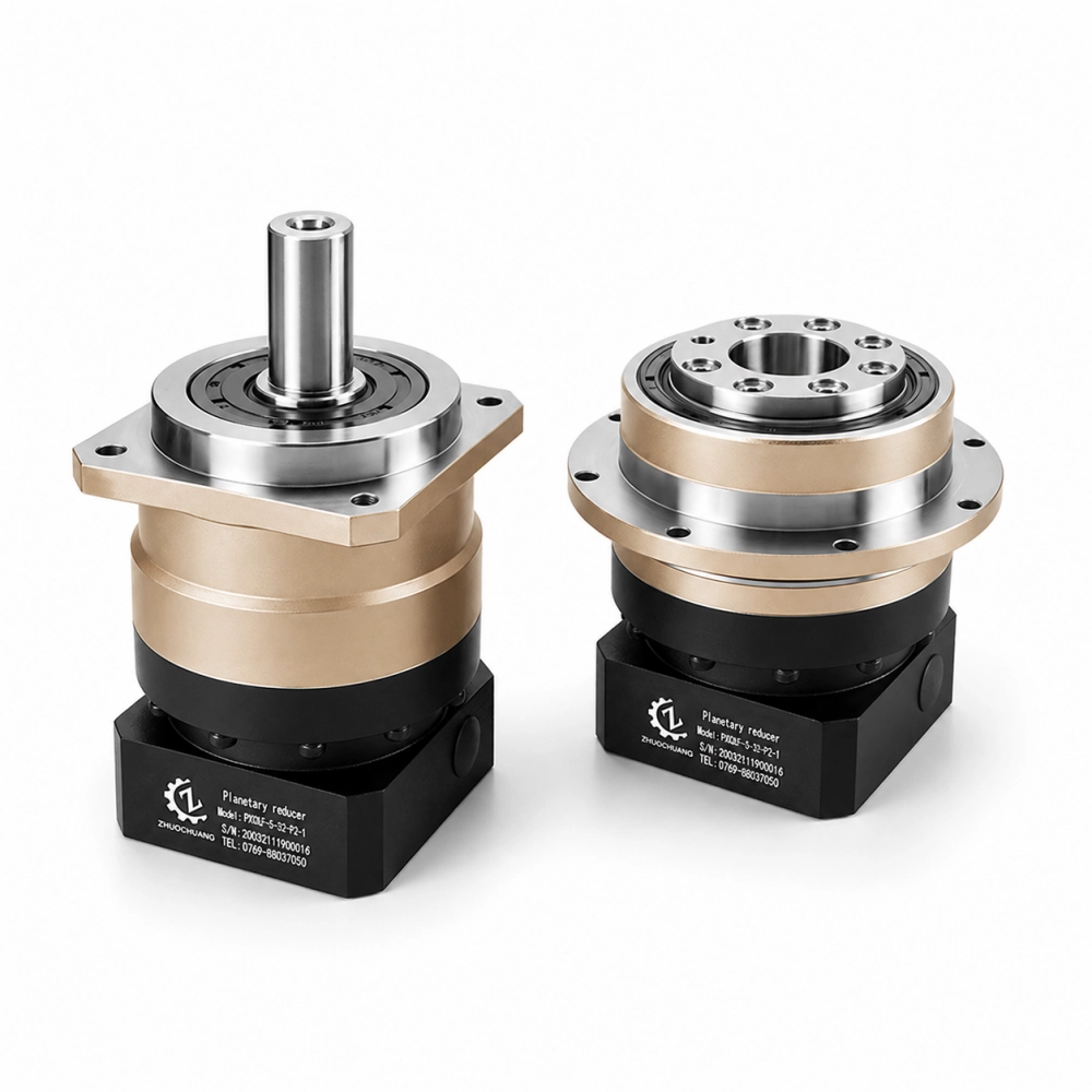
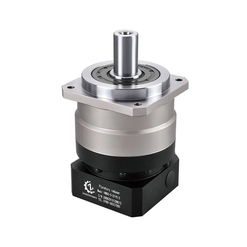
A conventional inline planetary gearbox keeps the motor input and gearbox output on one centerline. Its sun gear, planet gears, ring gear and carrier create a coaxial power path rather than the offset arrangement described above. That architecture is widely used in servo automation where compact torque transmission, controlled backlash and repeatable motion are important.
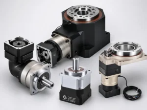
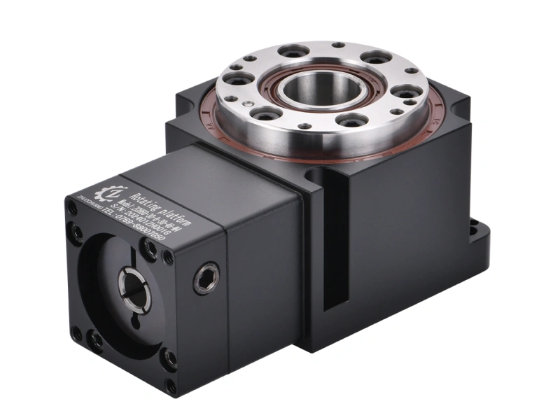
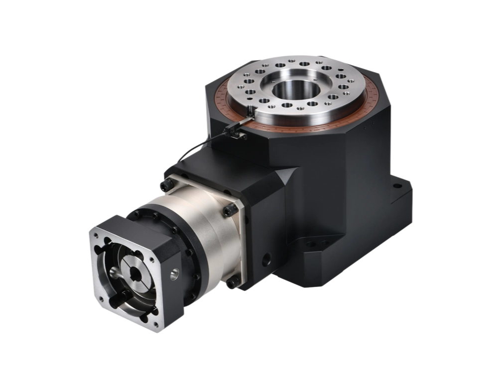
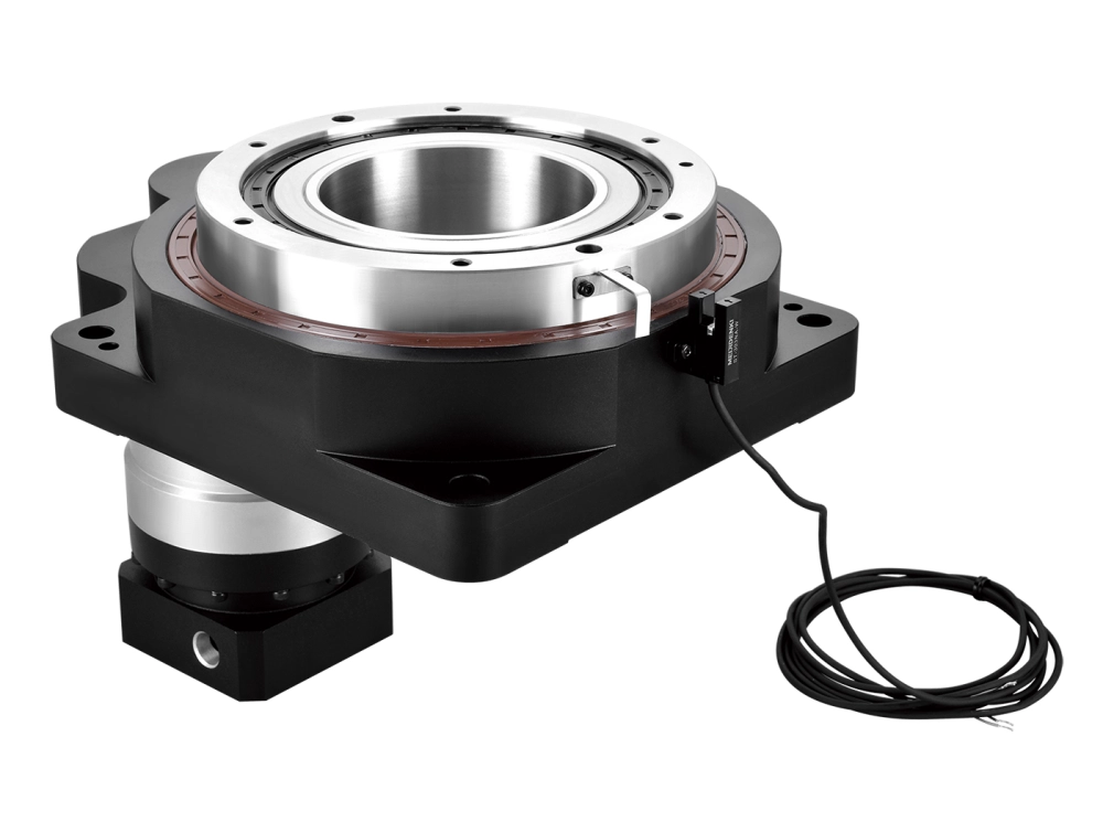
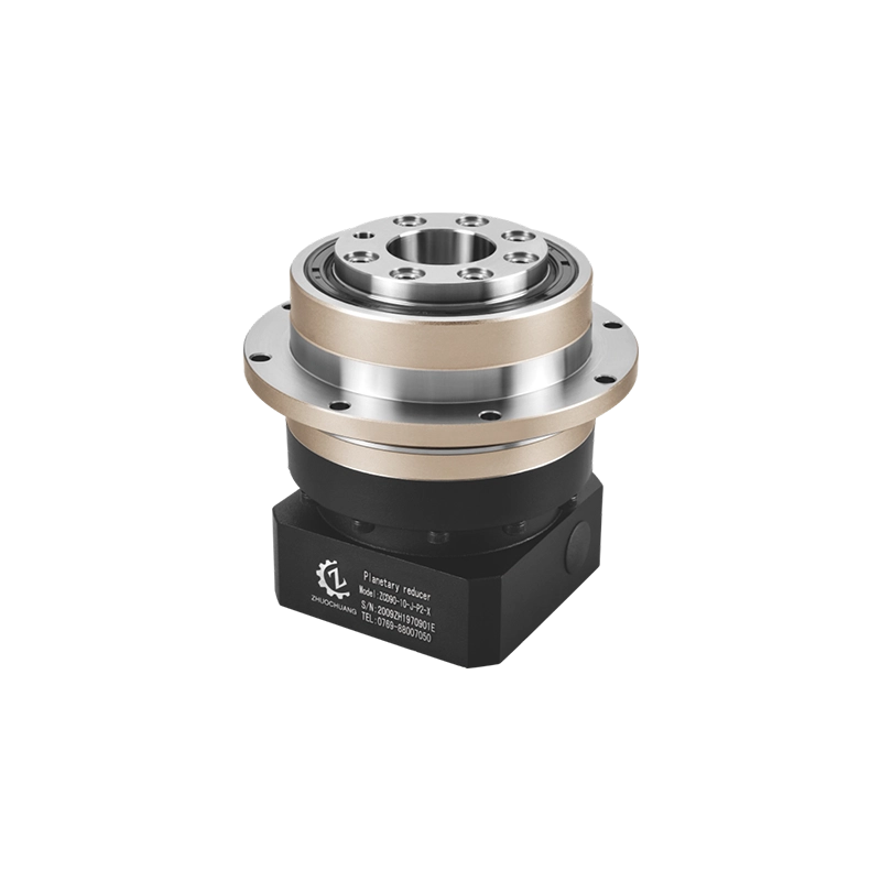
Dongguan Zhuochuang Precision Machinery Co., Ltd. manufactures precision planetary gearboxes and hollow rotary tables. We do not present our products as conventional parallel-shaft industrial reducers. For an offset-versus-coaxial machine decision, read Parallel Shaft Reducer or Planetary Gearbox? Start With the Machine Layout.
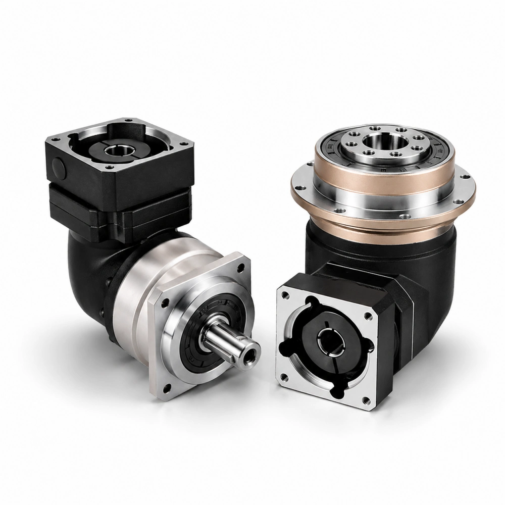
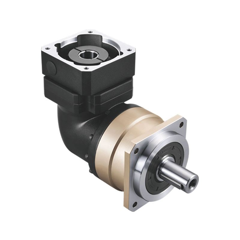
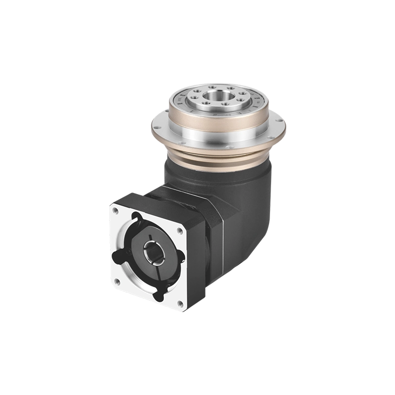
If the machine needs coaxial servo transmission, review our inline planetary gearboxes. If the motor must turn 90 degrees because axial space is restricted, a right-angle planetary gearbox may be more appropriate. Final selection should use the complete motor model, torque cycle, ratio, backlash target, external loads and installation drawing.
Request Planetary Gearbox Selection Support
Related Reading
- Parallel Shaft Reducer vs Planetary Gearbox — compare offset and coaxial machine layouts.
- Double Reduction Gearbox — ratio and efficiency across two consecutive stages.
- Planetary Gearbox Types — understand inline, right-angle and other planetary configurations.
Technical Reference
For engineering terminology and design guidance covering spur and helical gearing with parallel axes, see AGMA 917-B97, Design Manual for Parallel Shaft Fine-Pitch Gearing. The exact gearbox model must still be evaluated using its current manufacturer drawings and ratings.