
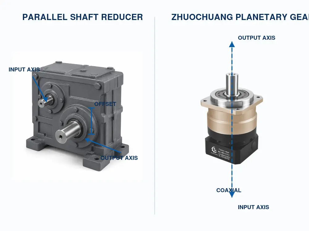
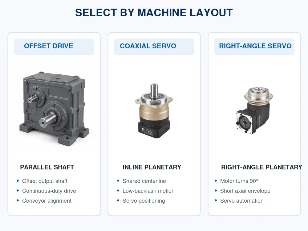
When a machine designer compares a parallel shaft reducer with a planetary gearbox, the first question should not be “Which gearbox has the higher ratio?” It should be “Where must the output shaft sit relative to the motor?” A parallel-shaft design places the input and output axes parallel but offset. An inline planetary gearbox keeps them coaxial. That single geometric difference affects the machine envelope, coupling arrangement, mounting plate, driven-shaft position and service access.
Quick answer: choose a parallel shaft reducer when an offset output helps align the drive with a conveyor, mixer, lift or existing shaft line. Consider a precision planetary gearbox when the machine needs a compact coaxial servo drive, low backlash, high torsional stiffness and repeatable positioning. Neither layout is universally better; the correct choice follows the load, motion profile and available space.
Start With the Shaft Centerline, Not the Catalog Name
The word “parallel” describes the relationship between two rotational axes. In a typical parallel shaft gearbox, the motor-side input shaft and the machine-side output shaft point in the same general direction but do not share one centerline. Spur or helical gear pairs transmit power across that offset. The exact distance between the axes comes from the gear geometry and housing design.
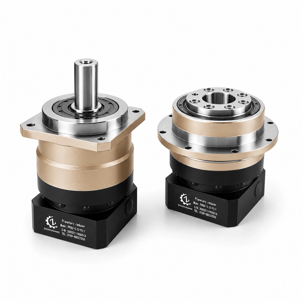
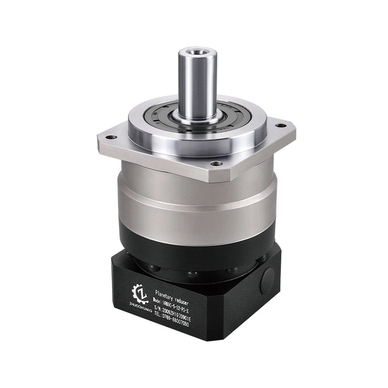
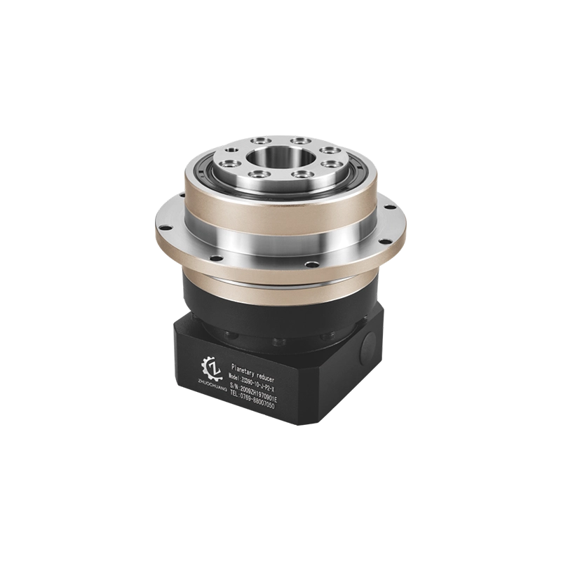
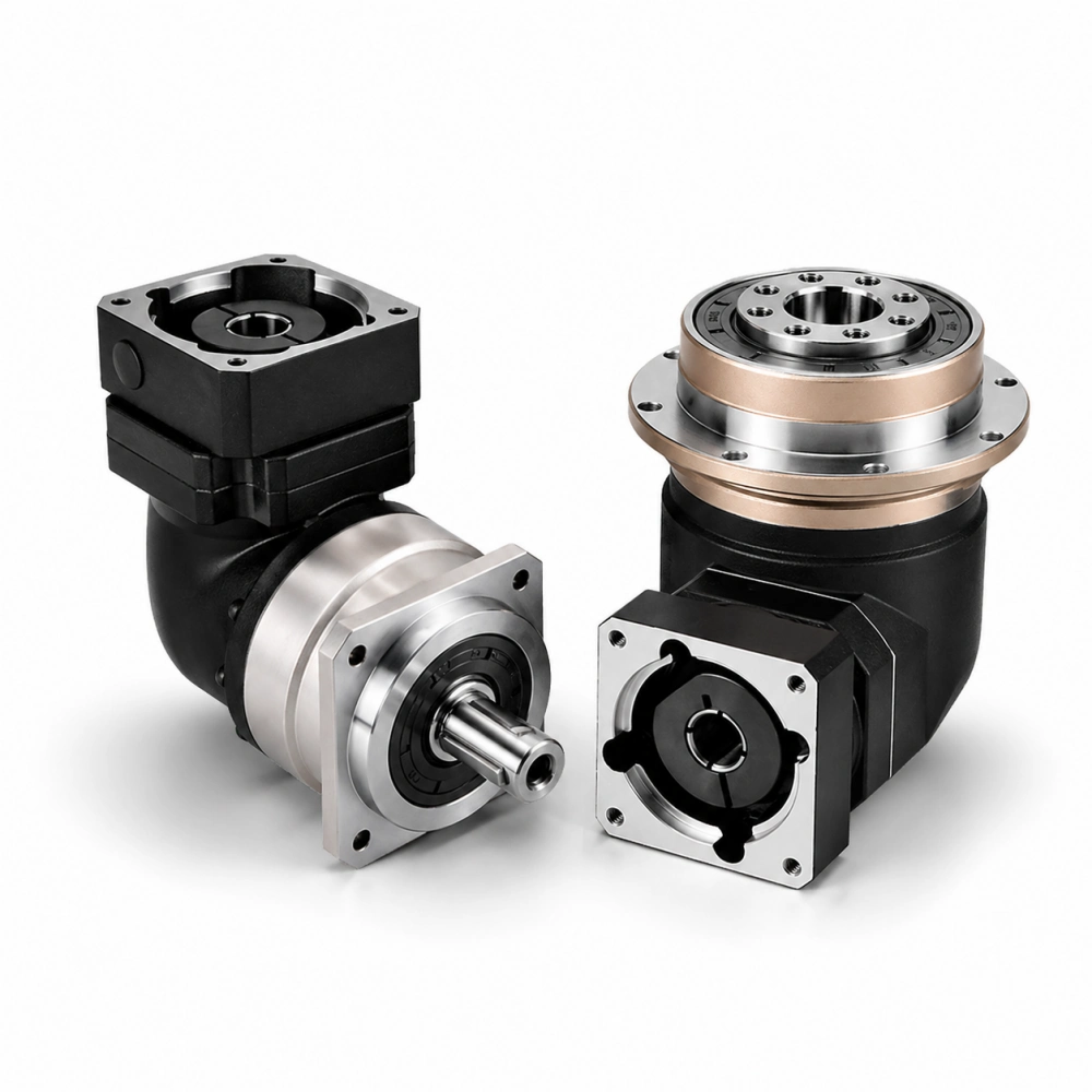
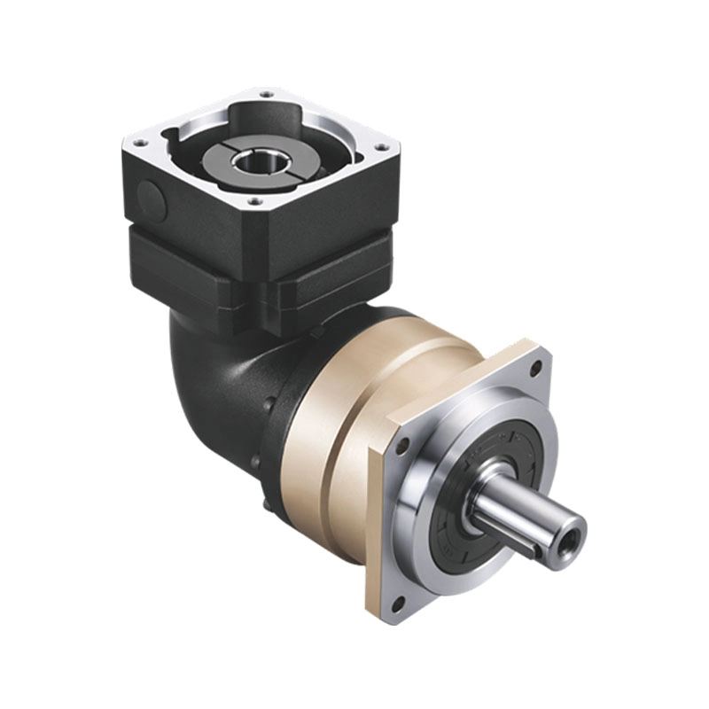
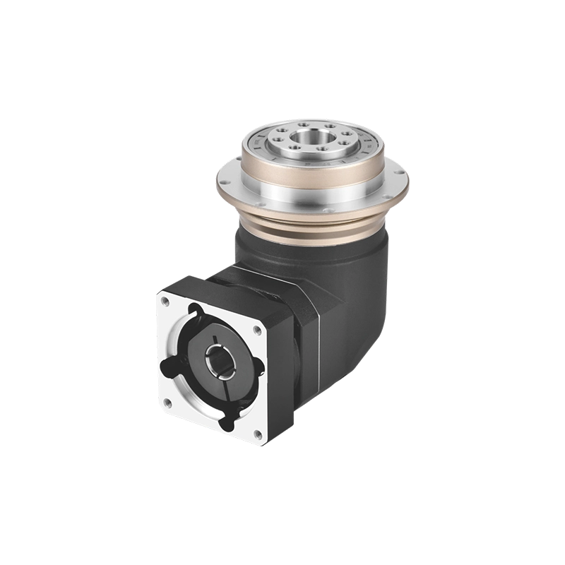
A planetary gearbox uses a sun gear, planet gears, a ring gear and a carrier. In a conventional inline arrangement, the motor input and gearbox output are coaxial. Multiple planet gears share load around the center, allowing substantial torque capacity in a compact cylindrical envelope. A right-angle planetary gearbox adds a bevel stage ahead of the planetary reduction when the motor must turn 90 degrees.
This distinction is more useful than treating parallel shaft speed reducer, parallel shaft gear reducer and planetary gearbox as interchangeable search terms. They can all reduce speed and multiply usable torque, but they solve different packaging and motion-control problems.
Read the Two Layouts From the Machine Frame
Imagine looking at the motor and driven shaft from the side of a machine. With a parallel shaft reducer, the motor centerline may sit above, below or beside the output centerline. This offset can place the motor clear of a conveyor frame, align the output with an existing driven shaft or shorten the overall axial projection of the drive package.
With an inline planetary gearbox, the motor, gearbox and driven component form one straight axis. This arrangement is natural for a servo-driven ball screw, rack-and-pinion axis, indexing mechanism or other system where the motor and output can share a centerline. It also simplifies the conceptual power path: motor, gearbox and load are arranged coaxially.
A parallel shaft reducer gearbox is therefore not automatically “more compact” or “less compact.” It may be shorter in one direction but taller or wider in another. The same applies to a planetary unit. Compare the complete installed envelope, including motor length, coupling, mounting plate, cable connector, access for bolts and space needed to remove the motor.
Where an Offset Output Actually Helps
The offset is valuable when it removes another component or makes the machine easier to arrange. A conventional parallel gear reducer may place its output shaft directly in line with a conveyor head shaft while keeping the motor away from the belt, guards or supporting structure. In processing machinery, the same layout may position the motor above a washdown zone or outside a crowded frame.
Offset geometry can also provide multiple mounting orientations, depending on the manufacturer’s housing and lubrication limits. However, buyers should not infer allowable orientation from a product photograph. Oil level, breather position, bearing lubrication and thermal behavior must be checked for the specific model.
Do not choose a parallel shaft speed reducer merely because the machine drawing has spare space beside the load. First confirm whether the output is solid-shaft, hollow-bore, shrink-disc or flange style; whether an external coupling is required; and whether the reducer bearings can carry the applied radial and axial forces. An offset that looks convenient can still create an awkward belt pull, overhung sprocket load or maintenance problem.
Three Machines, Three Different Answers
A continuously running conveyor
A conveyor often benefits from a robust parallel shaft gear reducer or geared motor when its output can align directly with the conveyor shaft. The selection usually emphasizes continuous torque, service factor, thermal capacity, mounting method, sealing and overhung load. High positioning precision may not be the primary requirement.
If the conveyor is a high-speed indexing conveyor synchronized by a servo motor, the decision changes. Acceleration torque, reflected inertia, reversing behavior and backlash become more important. A planetary gearbox may be a better fit even though a conventional parallel shaft reducer could satisfy the basic speed ratio.
A servo-driven positioning axis
For a rack-and-pinion axis, rotary indexer or automated inspection station, the drive must repeatedly stop at a commanded position. Here, a precision planetary gearbox can offer the coaxial package, controlled backlash and torsional stiffness expected in servo motion. Ratio alone cannot predict positioning quality; tooth accuracy, bearings, carrier rigidity, assembly control, coupling stiffness and machine structure all contribute.
A machine with restricted axial space
If a straight motor-and-gearbox assembly projects too far from the frame, a parallel shaft gearbox may fold the motor alongside the output line. A right-angle planetary gearbox is another possibility when a 90-degree motor orientation suits the machine better. These two solutions are not geometrically equivalent, so compare the actual installation drawing rather than selecting from the terms “offset” or “right angle.”
Engineering Comparison: Parallel Shaft Reducer vs Planetary Gearbox
| Decision point | Parallel shaft reducer | Planetary gearbox |
|---|---|---|
| Input and output axes | Parallel and offset | Normally coaxial in an inline model |
| Typical gear arrangement | Spur or helical parallel-axis stages | Sun, planets, ring gear and carrier |
| Packaging advantage | Can move the motor away from the driven centerline | Compact torque transmission on one centerline |
| Common application emphasis | Conveying, processing and general industrial drives | Servo automation, indexing and precision motion |
| Precision | Depends on the selected series and design | Precision series are available with controlled backlash |
| External load check | Radial, axial and overhung loads must be verified | Radial, axial and moment loads must be verified |
| Motor integration | May be a separate reducer or an integrated geared motor | Commonly adapted to a servo or stepper motor |
| Best selection evidence | Reducer drawing, load data and duty cycle | Gearbox drawing, motor model and motion profile |
The table describes common engineering tendencies, not universal ratings. A specific parallel shaft reducer gearbox may outperform a particular planetary model in one application, while the opposite may be true in another. Rated torque, peak torque, efficiency, permissible input speed, backlash, noise, bearing capacity and thermal limits must come from the manufacturer’s data for the exact size and ratio.
Precision Is Not a Label on the Housing
Search results sometimes imply that every planetary gearbox is precise and every parallel shaft gear box is intended only for basic power transmission. That is too broad. Gear quality, tooth form, bearing arrangement, shaft stiffness, housing rigidity, lubrication and assembly tolerance determine actual performance.
For servo automation, ask for the stated backlash grade and understand the test conditions. Also check torsional stiffness, no-load running torque, transmission error where relevant and the effect of the driven mechanism. A low-backlash gearbox cannot correct clearance in a coupling, pulley, rack, bearing seat or machine frame.
Efficiency also needs context. Gear type, ratio, number of stages, lubricant, speed, load and temperature all matter. Do not use one generic efficiency value to calculate motor size or output torque for every parallel shaft speed reducer or planetary gearbox.
Parallel Shaft Is Not the Same as Shaft Mounted
These terms answer different questions. Parallel shaft describes the relative direction of the input and output axes. Shaft mounted describes how a reducer is supported and connected to the driven machine shaft. A gearbox can use parallel-axis gearing without being directly shaft mounted, and a shaft-mounted reducer may require a hollow bore, shrink disc, keyed connection and torque arm.
This article focuses on the offset-versus-coaxial layout decision. If your main question is whether the reducer slides onto the driven shaft or uses a separate base and coupling, read our guide to shaft-mounted speed reducers versus planetary gearboxes. Keeping these search intents separate prevents the mounting method from being confused with the internal shaft arrangement.
Where a Zhuochuang Planetary Gearbox Belongs
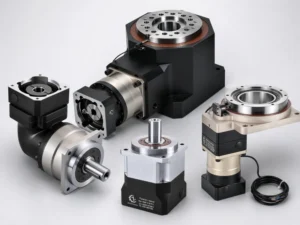
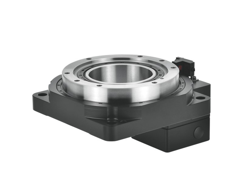
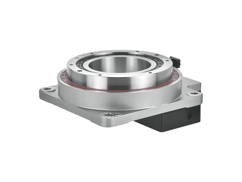
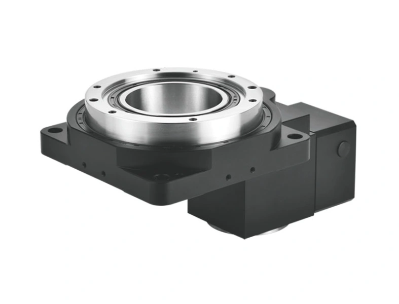
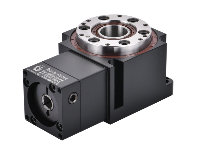
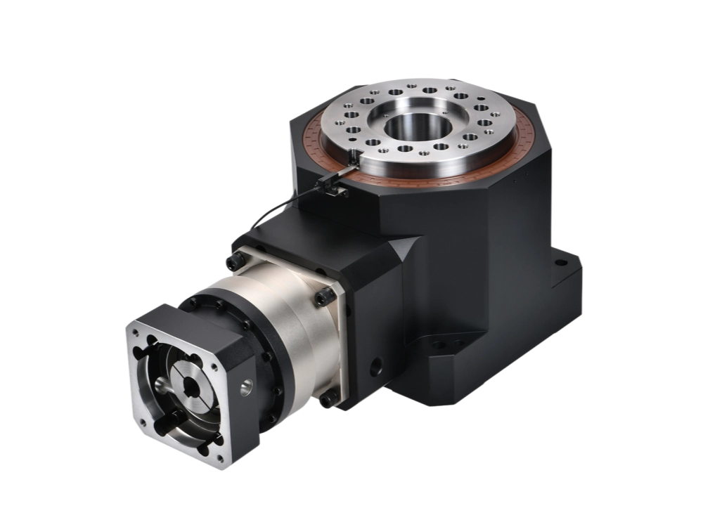
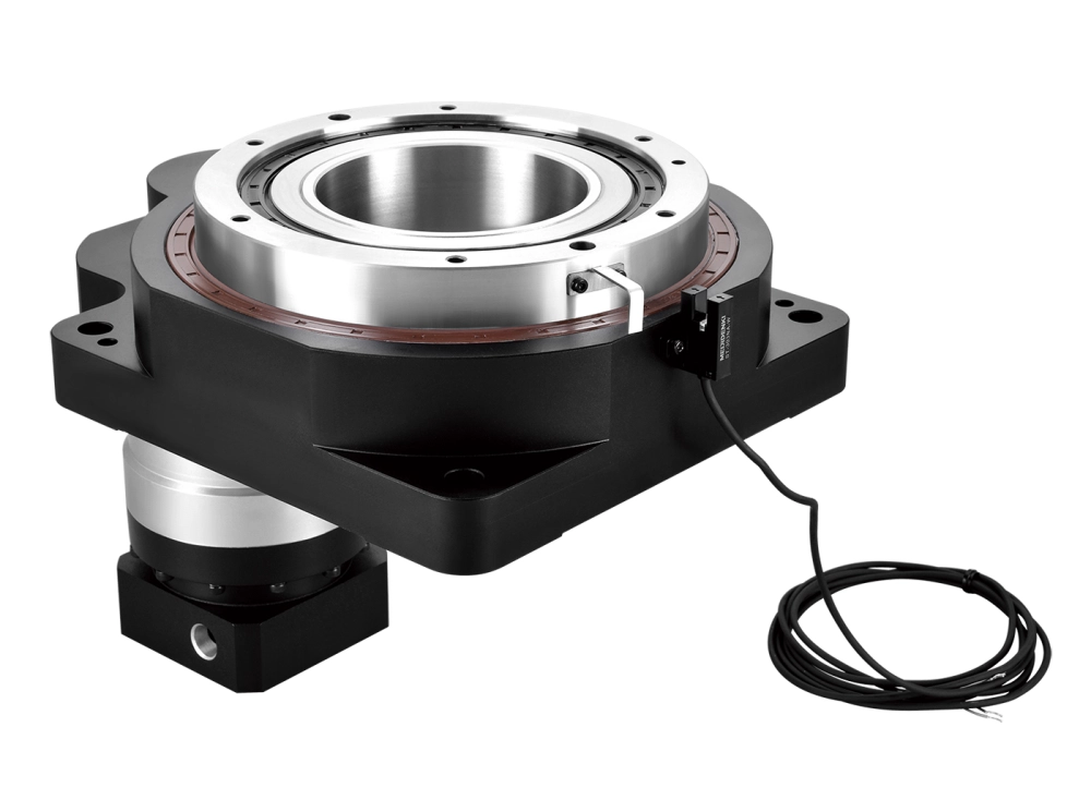
Dongguan Zhuochuang Precision Machinery Co., Ltd. manufactures precision planetary gearboxes and hollow rotary tables for industrial automation. We do not present our products as conventional parallel-shaft industrial reducers. Our relevant solution is a planetary gearbox selected for a servo or stepper motor when the application requires compact transmission, suitable ratio and torque, controlled backlash and a confirmed mechanical interface.
An inline planetary gearbox is the natural comparison when the motor and output should remain coaxial. When axial clearance is limited or the motor must turn away from the driven axis, a right-angle planetary gearbox may provide a more practical servo layout. Review the complete planetary gearbox range only after the machine geometry and motion requirements are known.
The decision should return to the application: if an offset output and general industrial duty define the project, request a suitable parallel shaft reducer from a manufacturer that rates that product for the load. If coaxial servo motion, repeatability and compact torque density define the project, a Zhuochuang precision planetary gearbox may be the appropriate direction.
Send the Layout, Not Just the Motor Power
A useful gearbox inquiry should include enough information to reconstruct the real operating condition:
- Motor brand and complete model number;
- Motor rated speed, maximum speed and shaft dimensions;
- Required output speed or reduction ratio;
- Continuous, acceleration, deceleration and emergency-stop torque;
- Duty cycle, starts per hour and operating time;
- Load inertia and required acceleration time for servo applications;
- Radial force, axial force, overhung distance and tilting moment;
- Required backlash and positioning repeatability;
- Preferred shaft relationship: offset, coaxial or right angle;
- Mounting orientation, available envelope and machine drawing;
- Ambient temperature, contamination, washdown or other environmental limits.
For planetary gearbox selection support, send these details through our contact page. A drawing with shaft centerlines and load positions is usually more informative than a request for “a 1 kW reducer.”
Request Planetary Gearbox Selection Support
Related Reading
- Shaft Mounted Speed Reducer vs Planetary Gearbox — mounting method, hollow bore and torque-arm differences.
- Planetary Gearbox Types — inline, right-angle and other configuration choices.
- Double Reduction Gearbox — when two practical reduction stages are used.
Technical Reference
For terminology and engineering guidance on spur and helical gearing with parallel axes, see AGMA 917-B97, Design Manual for Parallel Shaft Fine-Pitch Gearing. Final product selection must still use the current manufacturer data for the exact gearbox model, size, ratio and duty.