
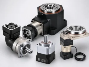
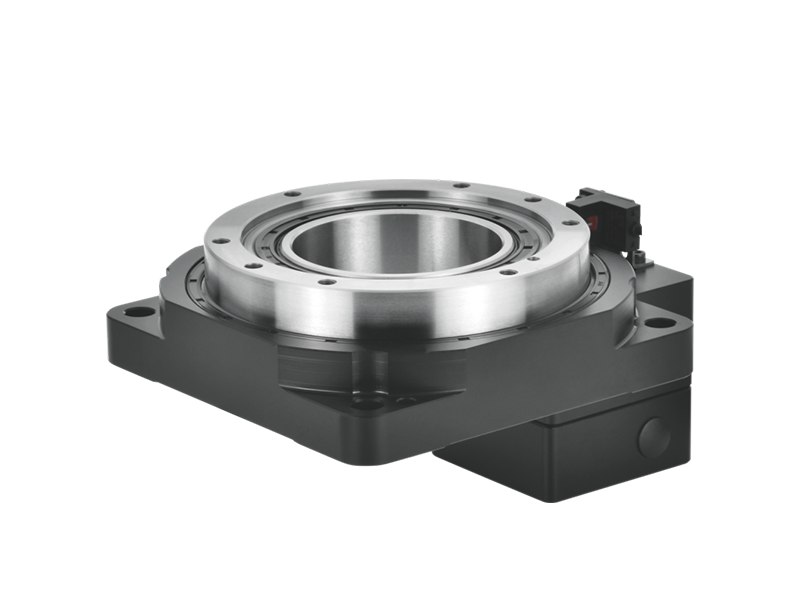
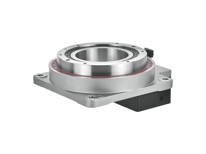
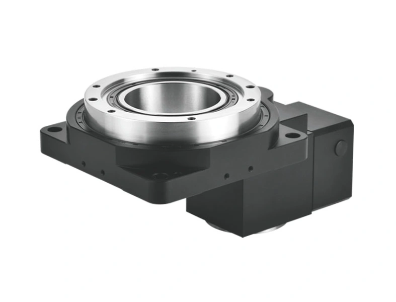
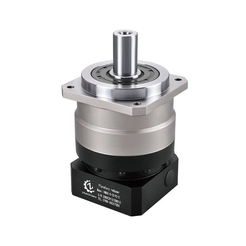
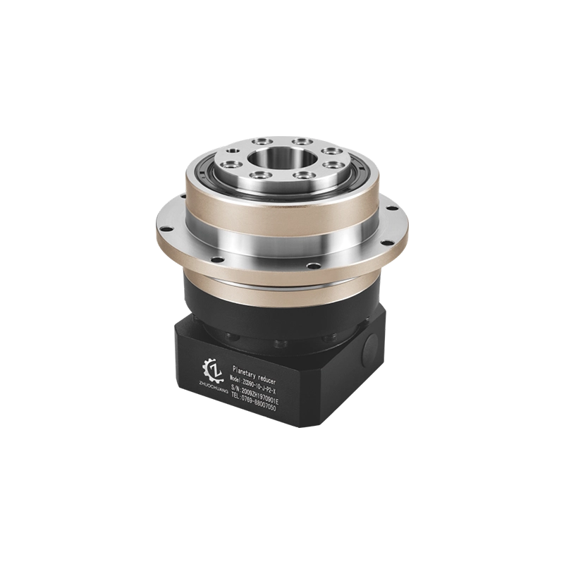
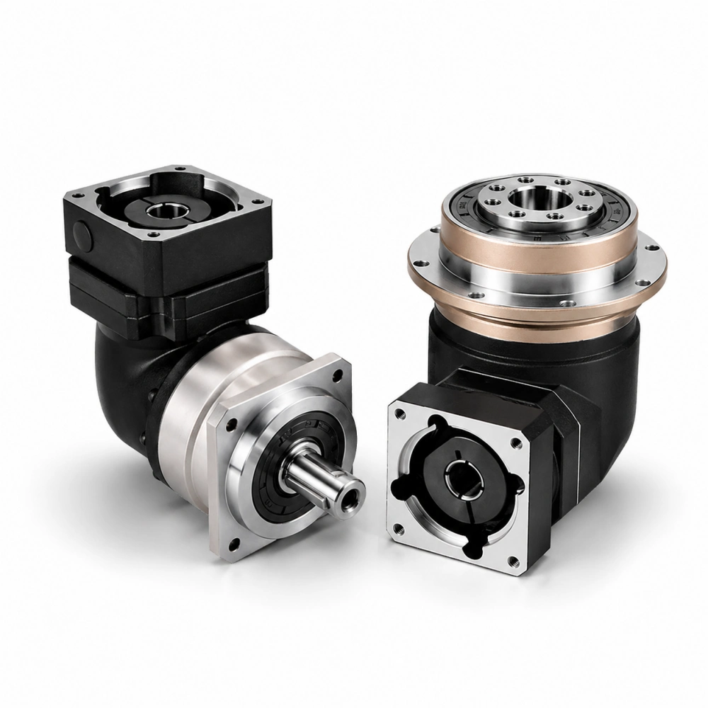
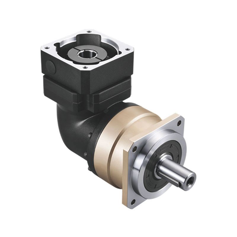
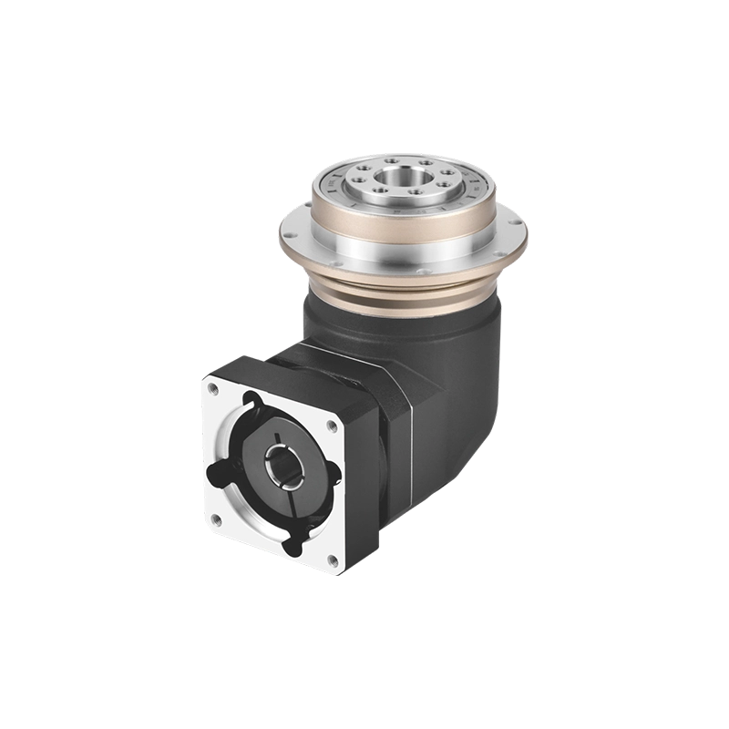
A gearbox can satisfy the required torque and ratio while its output support remains wrong for the machine. This often happens when a pulley, pinion, sprocket or cantilevered fixture applies force beyond the gearbox face. The motor may turn normally during a short test, yet the bearing system sees a load condition that the torque figure never described.
Planetary gearbox bearings do more than let shafts rotate. They keep rotating members aligned, carry internal gear reactions, support permitted external forces and help the gearbox retain stiffness under load. Their real capacity depends on the bearing arrangement, spacing, preload, shaft geometry, lubrication and housing support of the exact model.
What Planetary Gearbox Bearings Actually Support
Start at the machine load rather than inside the reducer. A timing pulley pulls on a belt. A sprocket carries chain tension. A rack-and-pinion axis pushes the pinion sideways. A fixture mounted away from the output face creates a moment as it accelerates. These forces enter the gear reducer output shaft or output flange and travel through the output support into the housing and machine frame.
The planetary gear mesh creates another load path. Torque passes among the sun gear, planet gears, carrier and ring gear according to the design. Bearings, pins and structural members hold those parts in position while the housing reacts forces. The exact arrangement varies by gearbox series, so a generic cutaway cannot prove the capacity of a specific product.
Important distinction: transmitted torque and allowable external output load are separate ratings. A model that can transmit the required torque may still be unsuitable for a distant pulley or an unsupported rotating arm.
Why Output-Shaft Distance Changes Bearing Load
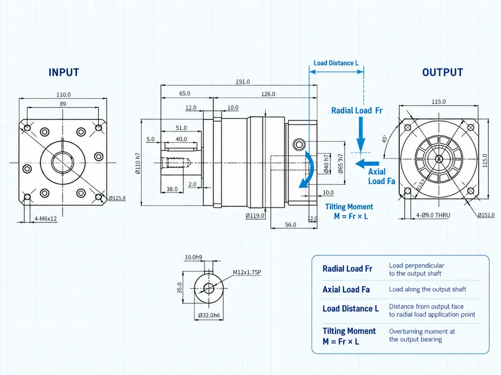
When evaluating planetary gearbox bearings, external force becomes more demanding as its line of action moves farther from the support. A simple first check is the bending moment created by force and distance:
If the radial force stays the same but the overhung distance doubles, the calculated moment also doubles. This is why a supplier needs both the load and its position. “The pulley load is 500 N” is incomplete without pulley center distance, belt direction and the reference point used for the measurement.
The formula is a screening relationship, not a gearbox approval calculation. The manufacturer must evaluate the real bearing spacing, shaft deflection, housing stiffness, load direction, speed and duty. Combined radial and axial forces may also need to be converted into an equivalent bearing load using the factors appropriate to the installed bearing system.
Planetary Gearbox Bearings in Four Machine Layouts
The same gearbox can face very different bearing duty after the output connection changes. These four layouts show why selection should follow the actual machine drawing.
| Machine connection | Main bearing concern | Information the buyer should provide |
|---|---|---|
| Flexible coupling to a separately supported shaft | Alignment error and coupling reaction; external radial load may be relatively limited when installed correctly | Coupling type, shaft sizes, alignment tolerance and axial movement |
| Timing pulley mounted on the gearbox output shaft | Belt tension creates radial force and bending moment | Tight-side and slack-side tension, pulley diameter, belt direction and overhung distance |
| Pinion driving a linear rack | Gear-separation force, changing direction and output-shaft deflection can affect mesh quality | Pinion pitch diameter, tangential force, pressure angle, mounting direction and acceleration cycle |
| Fixture or arm attached to an output flange | Radial force, axial force and tilting moment may act together during acceleration or emergency stop | Mass, center-of-gravity offset, orientation, acceleration and external support arrangement |
A direct flange connection can look compact, but compact does not mean load-free. The flange mounted planetary gearbox guide explains how pilot diameter, bolt circle and tilting moment affect that interface. This article stays with the bearing load path rather than repeating flange geometry.
Input and Output Bearings Do Different Jobs
The input and output duties of planetary gearbox bearings differ because the two sides face different speeds, torque levels, interfaces and external loads.
The gear reducer input shaft primarily receives motor motion through an adapter, coupling or clamping connection. Its support must maintain alignment at the permitted input speed and accommodate forces created by the input interface and internal gearing. Excessive motor-shaft misalignment can add unintended bearing load, heat and vibration before the output load is considered.
The output side normally faces higher transmitted torque after reduction and may also receive loads from the driven machine. Output support therefore needs to be evaluated against the real shaft or flange connection. Bearing spacing is important because a wider, well-supported arrangement can resist moment differently from a compact arrangement with another geometry. That does not make one arrangement universally better. It means catalog limits are specific to the design.
Preload and internal clearance also involve a balance. Appropriate control can improve positional stability and reduce unwanted movement. Excessive preload can increase friction and heat. Insufficient support or clearance control can allow deflection that affects seals, gear contact and repeatability. Buyers should specify the required result rather than prescribing an internal preload value without the manufacturer’s design data.
Bearing Capacity, Bearing Life and Output Stiffness Are Not the Same
A bearing arrangement may remain below its calculated load limit while the output still deflects more than the machine can accept. This matters in vision inspection, dispensing, robotic tooling and rack-and-pinion positioning, where a small angular or radial movement at the gearbox can become a larger error at the tool point.
Load capacity asks whether the support can carry a stated force or moment under defined conditions. Rating life estimates fatigue performance from load, speed and bearing data. Stiffness describes how much the output moves elastically under load. They influence one another, but one number cannot replace the others.
This distinction also explains why the question “how to select the right bearing for a gear reducer” cannot be answered from bearing size alone. The gearbox designer must consider bearing type, spacing, fit, preload, shaft diameter, housing rigidity, gear reactions, lubrication and assembly accuracy. The machine designer should provide the load case and required output behavior rather than nominate a bearing from its outside diameter.
For a positioning axis, ask how backlash and stiffness are specified and whether the figures apply at no load or under a defined torque. For a pulley or pinion drive, ask for permitted radial load at the actual overhung distance. For a flange-mounted arm, ask for allowable moment and whether an external support bearing is required. These questions connect the catalog data to the machine result.
What Bearing Ratings Can and Cannot Tell You
Catalog data for planetary gearbox bearings may include allowable radial load, allowable axial load or moment capacity. Before comparing numbers, check where the force is applied, at what speed, for which service life and under what mounting conditions. Two values with different reference distances or calculation assumptions are not directly comparable.
Bearing basic rating life is statistical. ISO 281 defines methods for dynamic load ratings and basic rating life of rolling bearings. A calculated bearing value is not automatically the service life of the assembled gearbox. Lubrication, contamination, temperature, alignment, shock loading, shaft and housing fits, gear forces and the operating cycle can change the result.
Static conditions matter as well. A stationary axis can experience a high emergency-stop load or impact that damages a contact surface even when average operating load is low. Ask whether the published value is a continuous operating limit, a peak limit, a static limit or a calculation reference. Do not multiply a catalog value by an assumed safety factor and treat the result as approved capacity.
Warning signs during design review
- The gearbox was selected from motor power and ratio without any output-load drawing.
- A large pulley or pinion is mounted at the end of a long shaft extension.
- The machine uses belt tension, but the RFQ lists only transmitted torque.
- An arm or fixture is attached directly to the output without a defined tilting moment.
- The application reverses rapidly, but only steady-state load is provided.
- An external support bearing appears in one drawing revision but not another.
- The buyer compares radial-load numbers measured at different distances.
These signs do not prove that a gearbox will fail. They show that the information is insufficient to approve the output support.
How to Specify Planetary Gearbox Bearings in an RFQ
A buyer normally does not need to choose the internal bearing part number. The better approach is to describe the operating condition clearly and let the gearbox manufacturer verify the complete support system.
- Identify the motor: provide the brand, complete model, rated speed, maximum speed, shaft diameter and flange dimensions so the motor interface can be checked against the gear reducer input shaft.
- Define motion: required ratio or output speed, direction changes, positioning cycle and starts per hour.
- Provide torque: continuous torque, acceleration and deceleration torque, peak duration and emergency-stop torque.
- Show the output connection: identify whether the driven component connects to the gear reducer output shaft, output flange or a separately supported shaft, then show the coupling, pulley, sprocket, pinion, arm or fixture.
- Dimension the load position: distance from the gearbox output face to the force line or center of gravity.
- State external forces: radial force, axial force, belt or chain tension and tilting moment when known.
- Show external supports: bearings, rails or structures that carry part of the machine load.
- Define precision: allowable backlash, repeatability and stiffness requirement under the relevant load.
- Describe duty and environment: operating hours, ambient temperature, contamination, washdown and mounting orientation.
- Request confirmation: approved model, load reference point, mounting drawing and any application limits.
For available configurations, review the planetary gearbox range. Product dimensions and ratings must still be confirmed for the selected series, frame size and ratio.
One Drawing Can Prevent the Wrong Selection
Planetary gearbox bearings should be evaluated as part of the entire load path. Record what is attached to the output, where the force acts, how the axis moves and which external supports exist. Then compare the exact model’s permitted loads, reference distances and duty conditions. This approach gives the supplier enough information to check the gearbox instead of guessing from motor power, torque and ratio.