
A servo motor and gearbox combination can look correct in a quotation and still create trouble on the machine. The motor power is sufficient. The selected ratio produces the expected output speed. The gearbox torque rating appears to cover the load. Yet the adapter will not seat, the coupling slips, the axis vibrates or the system takes too long to settle after each move.
These failures are often treated as isolated installation problems. In reality, they usually begin earlier—when the motor drawing, load cycle, coupling arrangement or approved gearbox configuration is incomplete.
This article is not another general servo gearbox selection guide. It examines nine matching errors that appear during assembly, servo tuning and machine commissioning, together with the evidence needed to separate an interface problem from a sizing problem or control problem.
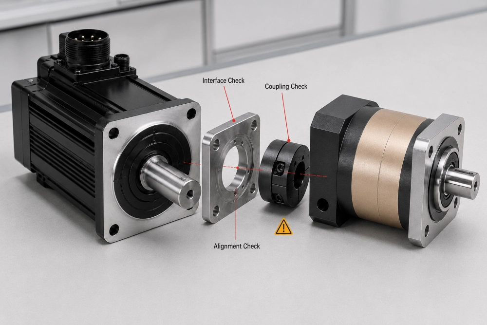
Start with the Symptom, Not an Immediate Conclusion
When a servo axis behaves poorly, the gearbox is often blamed first because it sits between the motor and load. Replacing it without identifying the actual source may leave the problem unchanged.
| Observed symptom | Possible matching issue | First evidence to check |
|---|---|---|
| Motor and gearbox cannot be assembled | Shaft, pilot, bolt pattern or adapter mismatch | Approved motor-interface drawing |
| Coupling slips during acceleration | Incorrect bore, insufficient engagement or tightening error | Coupling drawing and assembly record |
| Axis vibrates after tuning | Mechanical compliance, excessive inertia or loose connection | Motion trace and physical connection inspection |
| Gearbox becomes unusually hot | Excessive input speed, duty, preload or misalignment | Operating cycle and temperature trend |
| Position changes after direction reversal | Backlash, coupling movement or structural deflection | Output-side lost-motion test |
| Replacement motor does not fit | Same power but different mechanical interface | Old and new motor drawings |
A useful diagnosis proceeds from evidence. Check what changed, identify where movement or heat first appears, and confirm the mechanical configuration before changing servo parameters.
Error 1: Selecting the Gearbox from Motor Power Alone
Descriptions such as “750 W servo motor” or “1 kW servo” are not sufficient for gearbox matching. Two motors with the same power can have different rated speeds, peak torque curves, rotor inertia, flange dimensions, shaft sizes and brake arrangements.
Motor power also does not reveal how the machine operates. A steady rotary feed and a high-frequency indexing axis may use motors of equal power while creating very different gearbox loads.
At minimum, a servo motor gearbox review should begin with:
- Complete motor manufacturer and model number
- Rated and maximum motor speed
- Continuous and peak motor torque
- Motor rotor inertia
- Brake option, where applicable
- Mechanical drawing and shaft details
- Actual machine motion cycle
If the motor has not been finalized, the gearbox review should state which motor data remain provisional. This prevents an early gearbox model from being treated as fully approved after the motor changes.
Error 2: Checking Shaft Diameter but Ignoring Usable Shaft Length
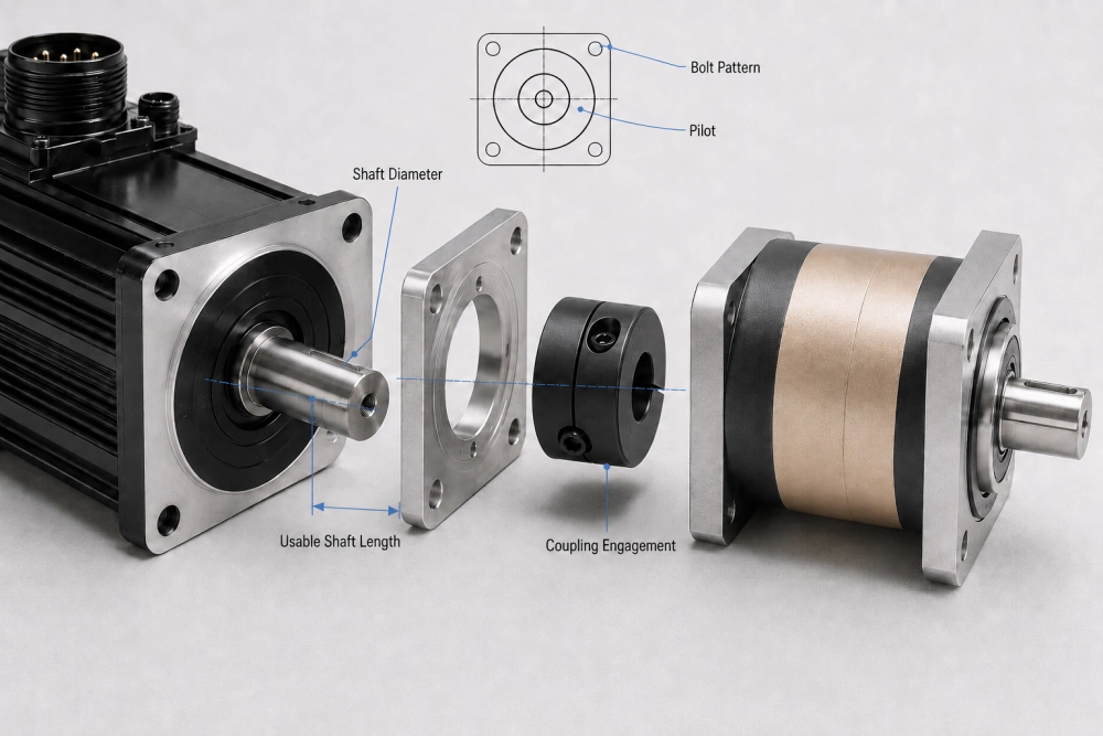
A matching shaft diameter does not guarantee a reliable connection. The coupling must engage enough usable shaft length to transmit acceleration and reversing torque without contacting a shoulder, radius or seal area.
Several installation errors can occur:
- The coupling reaches the shaft shoulder before the motor flange seats.
- The shaft enters only part of the clamping bore.
- A shaft key extends into an unsuitable part of the coupling.
- The coupling position leaves insufficient clearance inside the adapter.
- The motor shaft bottoms out before the components reach their intended position.
Record the shaft diameter, total extension, usable engagement length, keyway position and shoulder geometry. The coupling bore and clamping position should then be shown on the assembly drawing, not left to interpretation during installation.
Error 3: Treating the Motor Pilot as a Minor Dimension
The mounting bolts hold the assembly together, but the pilot normally provides the concentric location between the motor and adapter. If the pilot is incorrect, installers may still be able to insert the bolts while the motor axis remains offset from the gearbox input.
This can create coupling stress, uneven bearing load, noise, vibration and premature wear. Enlarging bolt holes is not a proper correction for an inaccurate locating diameter.
Before approving the adapter, confirm:
- Motor pilot diameter
- Pilot depth and available engagement
- Adapter locating bore
- Flange face clearance
- Bolt-hole spacing and screw size
For a broader comparison of servo, stepper and BLDC interfaces, see the guide that explains how to compare motor-family interface requirements.
Error 4: Approving the Adapter Before the Real Motor Drawing
Frame size and power are useful for early discussion, but an adapter should not enter production from assumptions about a “standard” motor. Even within the same nominal frame, shaft length, connector orientation, brake length or pilot details may differ.
A controlled process uses the actual motor drawing as an input and produces an assembly drawing that identifies:
- The complete motor model
- The proposed gearbox model and ratio
- The adapter configuration
- The input coupling or sleeve
- Critical locating and clearance dimensions
- Drawing revision and approval status
When the motor changes, the assembly must be reviewed again. Reusing an adapter solely because the new motor has the same rated power is one of the easiest ways to delay a replacement or production build.
Error 5: Using Peak Torque as if It Were Continuous Torque
Servo motors can deliver high short-duration torque during acceleration, braking and disturbance recovery. Gearbox ratings also distinguish between continuous operation and limited-duration overloads.
A quotation becomes risky when it compares the normal machine load with a maximum emergency rating or compares motor peak torque only with gearbox rated torque without considering how often the peak occurs.
Separate the motion cycle into identifiable periods:
- Acceleration
- Constant-speed operation
- Deceleration
- Dwell
- Direction reversal
- Emergency stopping
The objective is not simply to find the largest number. It is to determine whether the repeated torque and speed profile fits the gearbox’s allowable operating condition.
For the underlying calculations, use the separate guide on how to calculate ratio, output torque and reflected inertia. Keeping the calculations on that owner page prevents this troubleshooting article from competing with it.
Error 6: Treating Maximum Input Speed as a Continuous Rating
A maximum speed may describe a short operating condition rather than indefinite continuous running. The acceptable duration can depend on gearbox size, ratio, lubrication, mounting orientation, ambient temperature and the complete duty cycle.
If a gearbox operates near its speed limit for a large part of every cycle, observe the temperature trend instead of recording only one temperature reading. The important questions are whether the temperature stabilizes, whether it changes after several production cycles and whether the motor or gearbox is the original heat source.
An abnormal temperature rise can also result from:
- Misalignment between motor and gearbox
- Incorrect coupling position
- Excessive external load
- Over-tightened or distorted mounting
- Restricted airflow around the drive assembly
- A motion cycle different from the design assumption
Do not assume that every warm gearbox is incorrectly sized, but do not approve continuous production from a short unloaded test either.
Error 7: Trying to Tune Out a Mechanical Problem
A servo drive can compensate for many control-related effects, but tuning cannot repair a loose coupling, flexible bracket, inaccurate pilot or moving mounting surface.
Mechanical movement may appear in the control system as oscillation, following error, overshoot or long settling time. Increasing gains can make the symptom worse because the controller reacts more aggressively to movement that originates outside the motor.
Before repeated tuning changes, inspect:
- Motor and gearbox mounting fasteners
- Coupling clamping condition
- Adapter seating and pilot contact
- Gearbox output connection
- Machine bracket stiffness
- Pulley, pinion, ballscrew or driven-shaft movement
Major servo manufacturers also emphasize correct mechanical alignment. Rockwell Automation instructs installers to align couplings properly and keep axial and radial loads within motor limits, while Siemens notes that the required alignment accuracy depends on motor speed and coupling type. These principles support a simple troubleshooting rule: verify the mechanical chain before treating every motion problem as a controller problem.
Error 8: Ignoring the Load Applied Beyond the Gearbox Shaft
Output torque is only one part of gearbox loading. A pulley, sprocket, pinion or offset coupling can apply radial load, axial load and overturning moment to the output bearings.
The effect depends on both force and distance. Moving a pulley farther from the gearbox bearing can increase the bearing moment even when transmitted torque remains unchanged.
When the output connection is not directly supported by the machine, provide:
- Pulley, sprocket or pinion diameter
- Belt tension or estimated transmitted force
- Direction of radial and axial load
- Distance from the gearbox mounting face
- External bearing arrangement, if used
- Direction changes and shock conditions
A gearbox may pass a no-load commissioning test and still develop bearing problems after the belt is tensioned or the final tooling is installed. Testing the actual output arrangement matters.
Error 9: Failing to Lock the Approved Assembly Revision
The first machine may run successfully, but a later build fails because the motor, adapter or coupling has changed while the gearbox part description remains the same.
This is no longer a calculation problem. It is a configuration-control problem.
The approved servo motor and gearbox assembly should identify:
- Servo motor manufacturer and exact model
- Gearbox series, frame and ratio
- Adapter drawing and revision
- Coupling or sleeve bore
- Output configuration
- Special mounting orientation
- Approved sample or first-article reference
If any controlled item changes, review the affected interfaces instead of assuming interchangeability. This discipline is especially important for OEM projects using multiple approved motor brands or producing the same machine in several regions.
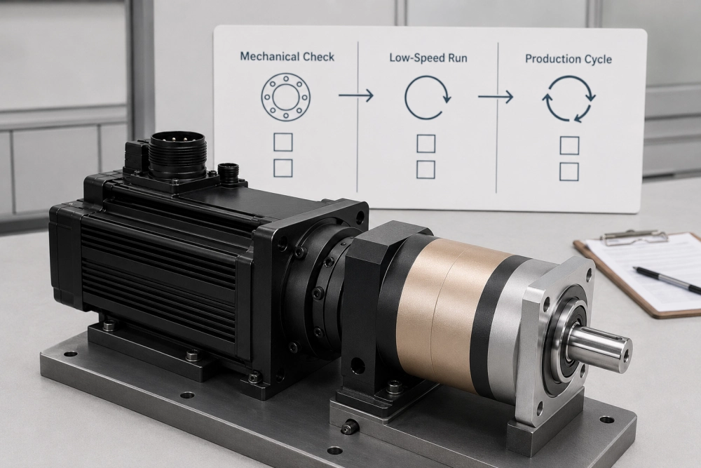
A Three-Stage Commissioning Check
Before power is applied
- Confirm the motor and gearbox identifiers against the assembly drawing.
- Check that the adapter seats without being pulled into position by the bolts.
- Verify coupling engagement and prescribed tightening method.
- Rotate the assembly carefully where the equipment procedure allows.
- Inspect cable orientation, brake clearance and machine interference.
During low-speed commissioning
- Run at low speed before applying the full production cycle.
- Observe noise, vibration, motor current and output behavior.
- Check direction, ratio and stopping position.
- Inspect for coupling movement or mounting looseness.
During the production-cycle test
- Use the real acceleration, speed, load and dwell sequence.
- Record whether temperature approaches a stable condition.
- Observe settling behavior after reversing and rapid stops.
- Recheck critical fasteners according to the machine procedure.
- Preserve the final approved motor, adapter, coupling and gearbox revisions.
When the Project Needs More Than a Catalog Adapter
A standard adapter is practical when the motor model, gearbox frame and required coupling are already supported. A custom interface may be appropriate when the project has an unusual pilot, shaft, connector clearance, output connection or installation envelope.
Customization should begin with controlled drawings rather than adjustments made during assembly. The manufacturer must determine whether the request changes only the adapter or affects the coupling, bearing loads, gearbox housing or internal transmission.
Buyers evaluating a non-standard interface can review the available adapter and output modification options for OEM equipment before sending project drawings.
Zhuochuang Support for Servo Drive Integration
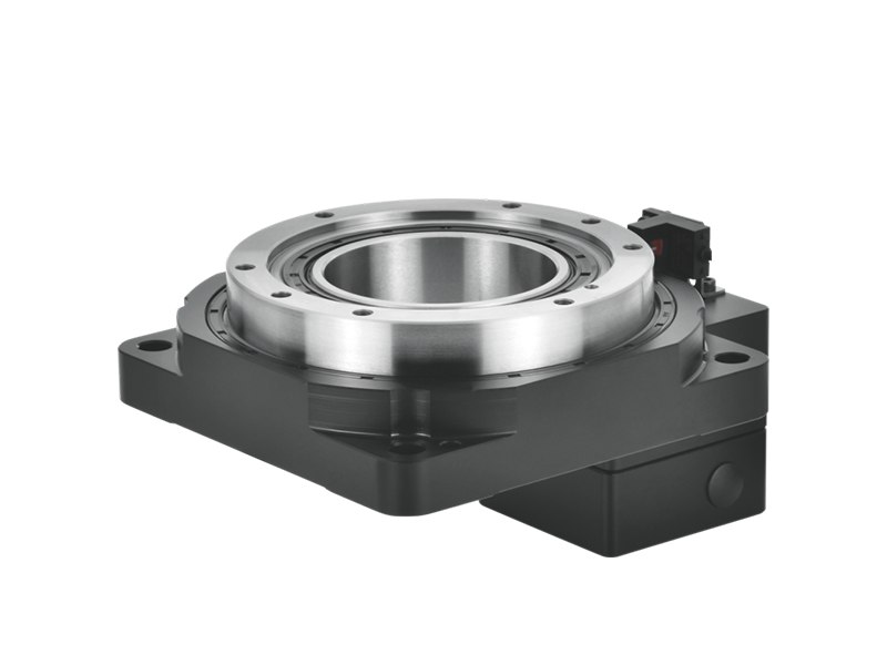
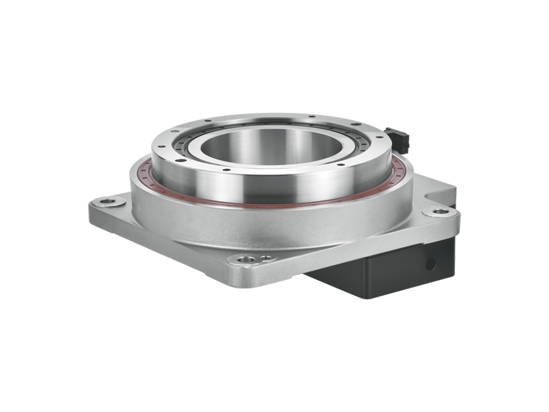
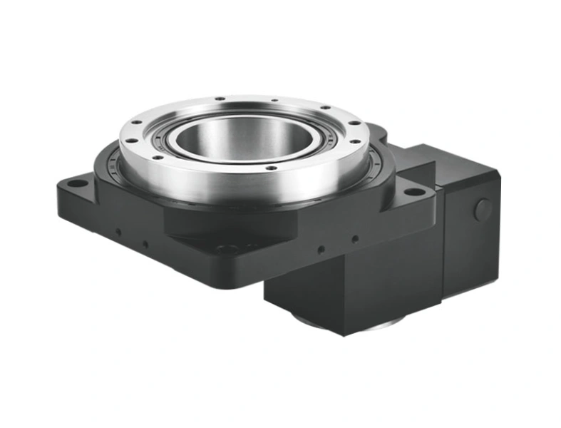
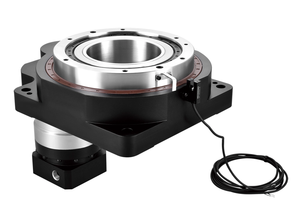
PlanetDrivePro is the official international website of Dongguan Zhuochuang Precision Machinery Co., Ltd. Zhuochuang manufactures precision planetary gearboxes and hollow rotary tables for automation and motion-control applications.
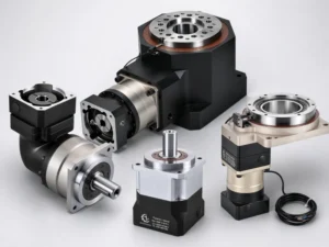
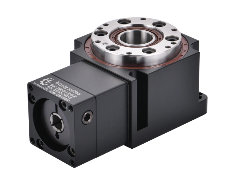
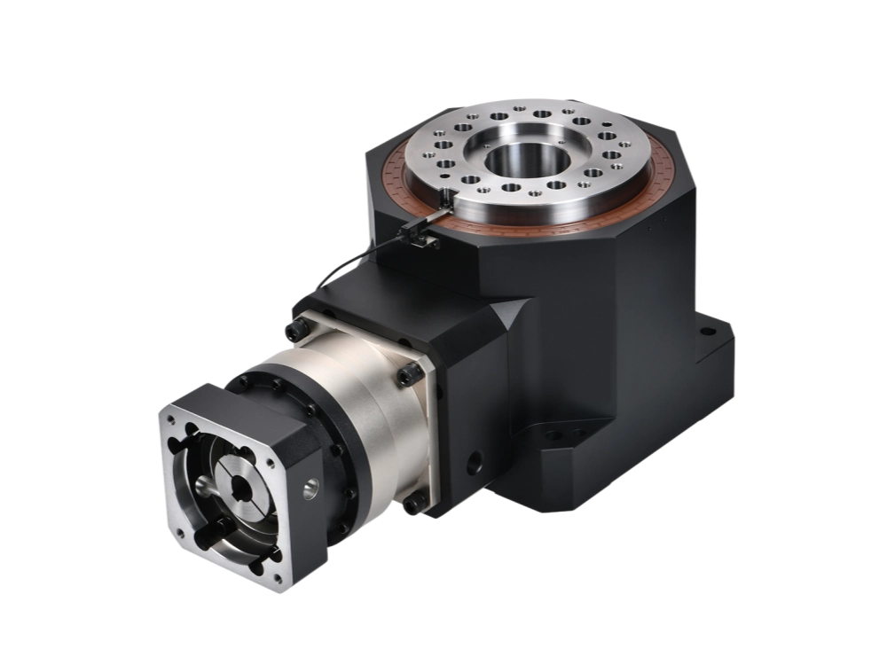
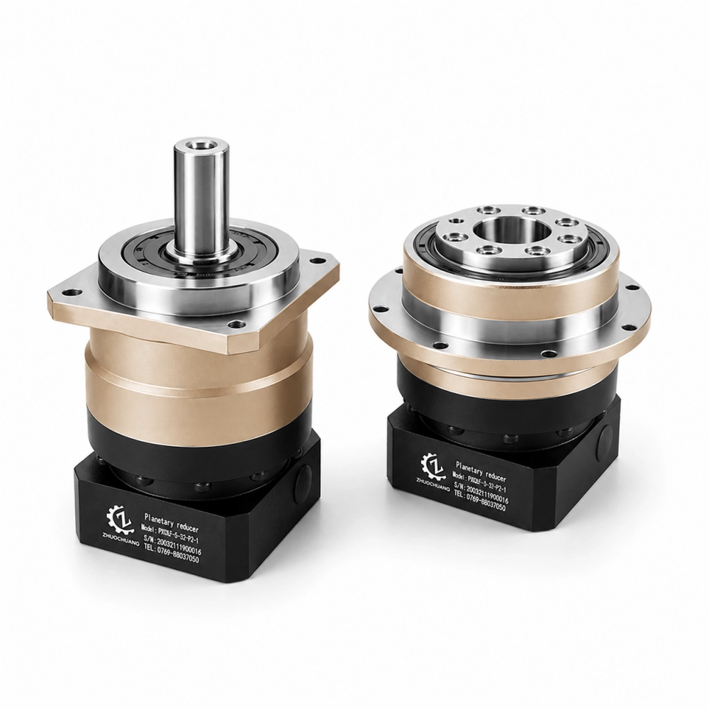
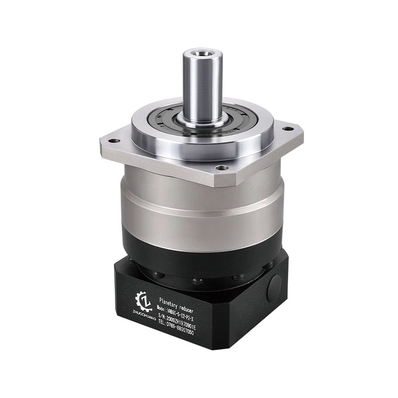
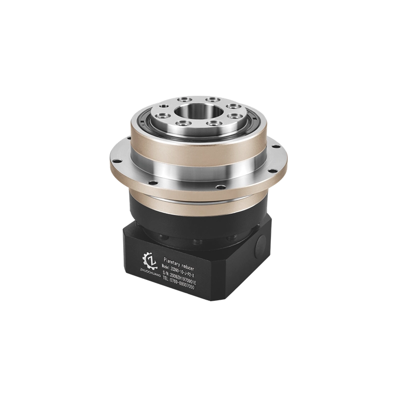
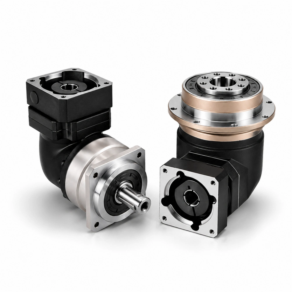
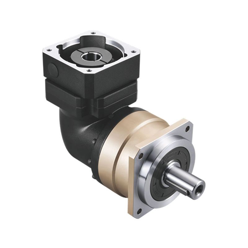
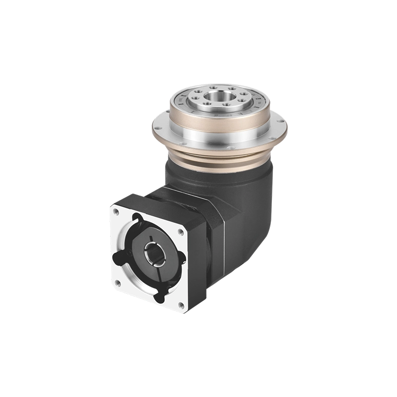
Our inline planetary gearbox range supports coaxial servo arrangements, while right-angle configurations allow the motor to be repositioned in compact machine layouts. Product selection can be reviewed from the Zhuochuang VRB inline range and the VRBR and ZCDR 90-degree configurations.
For OEM integration, a professional review should connect the motor drawing, operating cycle, gearbox configuration, adapter and output load. Sample validation and controlled assembly revisions then help preserve the approved result during repeat production.
Send the Assembly That Is Causing the Delay
If your servo motor and gearbox will not assemble correctly—or the axis develops vibration, heat, coupling movement or slow settling—send the motor drawing, gearbox model, adapter drawing, motion cycle and installation photographs.
For a new project, include the required ratio, continuous and peak torque, output load and available mounting space. This allows the interface and operating conditions to be reviewed together.
Frequently Asked Questions
Why does a servo motor and gearbox combination vibrate after installation?
Possible causes include excessive load inertia, mechanical compliance, an inaccurate pilot, coupling misalignment, loose mounting, an unsuitable ratio or aggressive control gains. Inspect the complete mechanical connection before changing the gearbox or repeatedly adjusting the servo.
Can two servo motors with the same power use the same gearbox adapter?
Not automatically. Motors with the same power can have different pilots, shafts, bolt patterns and usable shaft lengths. Compare the complete mechanical drawings before reusing an adapter or coupling.
Why does the servo motor run correctly without the gearbox but become unstable after assembly?
The assembled system adds gearbox inertia, load inertia, coupling behavior and mechanical compliance. It may also reveal alignment or mounting problems that are absent when the motor runs without a load.
Can servo tuning compensate for gearbox backlash?
Control settings may reduce certain visible effects, but they cannot remove physical clearance at the output. Backlash must remain within the machine’s mechanical error budget, especially when the axis reverses direction.
What should be checked when a coupling slips?
Confirm the motor-shaft diameter, coupling bore, engagement length, clamping method, surface condition, tightening procedure and peak torque. Also check whether the shaft bottoms out or contacts an unintended feature inside the adapter.
What information should I provide when asking Zhuochuang to investigate a matching problem?
Send the complete motor model and drawing, gearbox model, adapter and coupling drawings, motion cycle, continuous and peak torque, output connection, installation photographs and a clear description of when the symptom appears.
Related Technical Reading
- Determine which reducer architecture fits a servo-driven axis
- Understand settling behavior in compact 90-degree servo layouts
- Trace abnormal gearbox temperature before replacing components
Final Takeaway
A successful servo motor and gearbox match is more than a compatible power rating and reduction ratio. The motor shaft must engage the coupling correctly, the pilot must locate the adapter concentrically, the gearbox must tolerate the real torque and speed cycle, and the output bearings must support the installed load.
After the first machine is approved, the motor, adapter, coupling and gearbox revisions must remain linked. This combination of interface engineering, production-cycle testing and configuration control is what turns a workable prototype into a repeatable OEM drive assembly.