
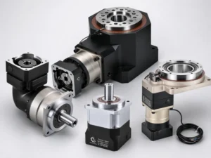
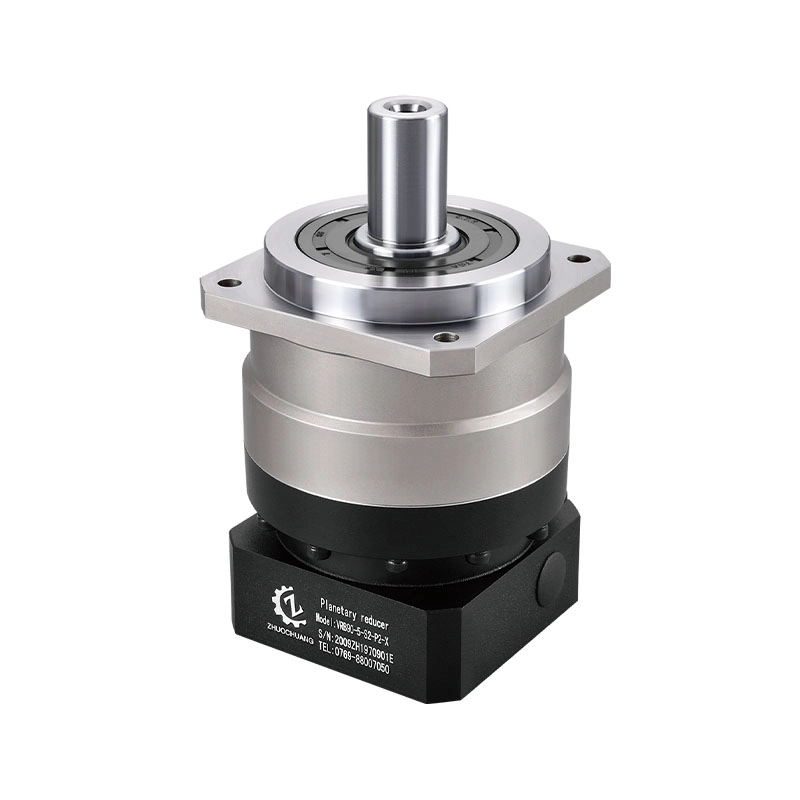
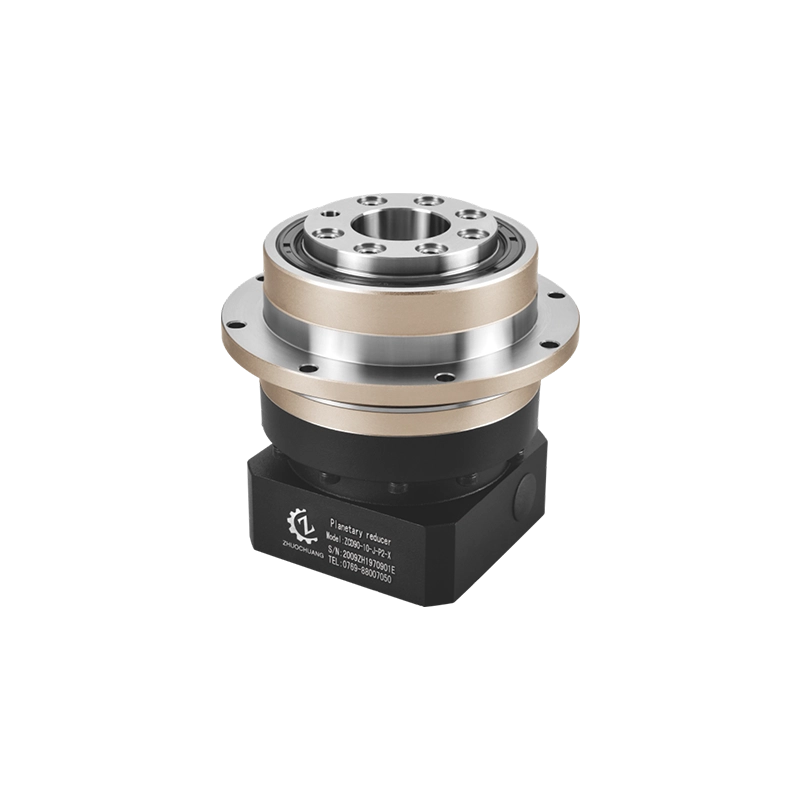
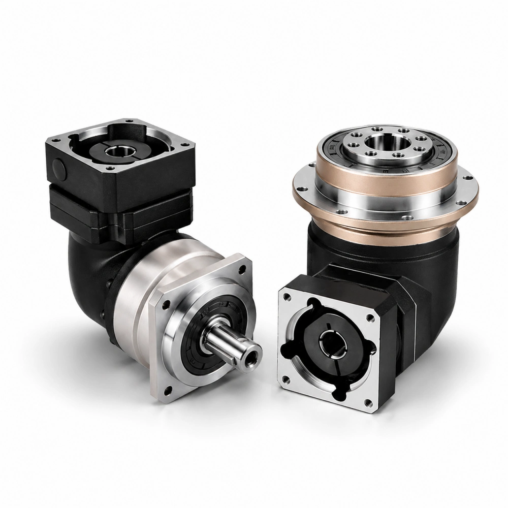
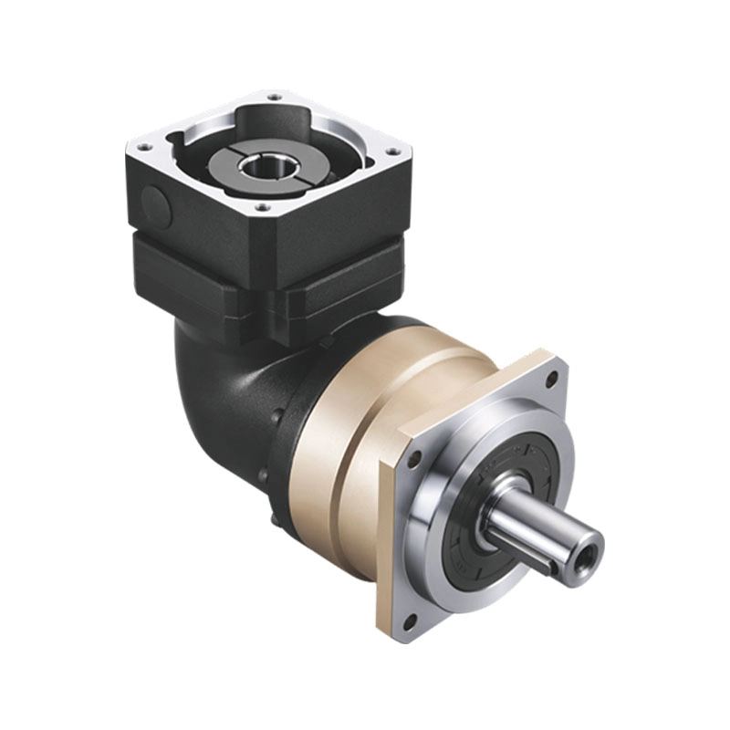
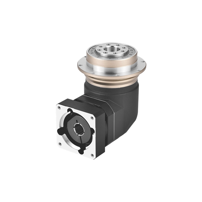
Searching for an electric motor gear reducer sounds straightforward, but the phrase can describe several very different drive systems. A conveyor powered by a standard AC gearmotor, a servo-driven packaging axis and a stepper-controlled rotary fixture may all use an electric motor and a reducer. Their requirements, however, are not the same.
For precision automation, selecting a reducer involves more than comparing motor power and gear ratio. The motor type, operating speed, acceleration torque, shaft dimensions, flange pattern, positioning requirement and installation layout must work together. A reducer can have sufficient rated torque and still be unsuitable because its input coupling does not match the motor shaft or its backlash is too high for the machine.
This guide explains how to match servo, stepper and BLDC motors with a precision planetary reducer. It focuses on the information that machine builders and equipment buyers should confirm before ordering a gearbox for electric motor applications.
What Does “Electric Motor Gear Reducer” Mean?
An electric motor gear reducer is installed between a motor and a driven mechanism. It reduces the output speed of the motor while increasing the torque available to the machine. Depending on the application, it may also improve load matching, increase positioning resolution and allow a more compact drive arrangement.
The terms electric motor speed reducer and speed reducer for electric motor are often used for the same general product. They do not, however, identify the exact reducer type.
A buyer using these terms may be looking for:
- A conventional industrial gearmotor for a continuous conveyor
- A precision planetary gearbox for a servo motor
- A planetary reducer for a stepper motor
- A compact reducer for a BLDC motor
- An inline or right-angle drive for automation equipment
Before selecting a product, first determine which motor is being used and what the machine must do. This prevents a general search term from leading to the wrong reducer technology.
First Identify the Electric Motor Type
The motor model is one of the first pieces of information a reducer supplier should request. A description such as “750 W electric motor” does not reveal enough about the motor’s speed, dynamic characteristics or mechanical interface.
Servo motor
Servo motors are commonly used in packaging machines, CNC equipment, robots, inspection systems and automated assembly lines. They provide closed-loop control of position, speed and torque.
A precision planetary reducer is often paired with a servo motor when the machine needs higher output torque, lower output speed, compact dimensions and controlled positioning. Backlash, torsional stiffness, acceleration torque and motor inertia can be important in these systems.
Stepper motor
Stepper motors are often paired with planetary reducers in indexing devices, compact positioning modules and cost-sensitive automation systems. Their available torque changes with operating speed, so the gearbox cannot be selected from holding torque alone. For NEMA frame compatibility, ratio selection, backlash and stepper-specific sizing, see our gearbox for stepper motor selection guide.
BLDC motor
Brushless DC motors are used in compact machines, AGVs, mobile equipment, pumps, medical devices and automated mechanisms. Their speed range and control method vary considerably between manufacturers.
When matching a BLDC motor with an electric motor speed reducer, confirm the rated speed, maximum speed, continuous torque, short-duration torque and shaft interface. A motor controller may limit the usable operating range even when the motor itself is capable of higher speed.
Standard AC induction motor
A standard AC induction motor can also be used with a reducer, but a precision planetary gearbox is not automatically the most economical solution. Large, continuously running conveyors, mixers and material-handling systems may be better suited to helical, bevel or worm gearmotors.
A planetary gearbox for electric motor use becomes more relevant when the machine requires compact size, high torque density, efficient transmission, frequent acceleration or better motion control.
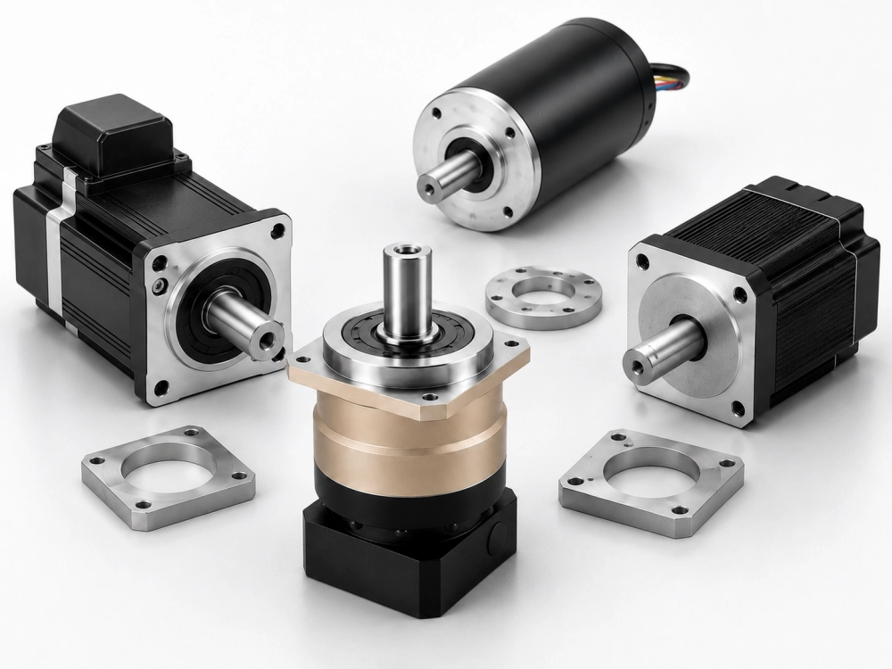
Which Motors Fit a Precision Planetary Gear Reducer?
A precision planetary reducer is most often selected for motor-driven systems where motion quality matters in addition to speed reduction. Typical examples include:
- Servo-driven packaging and labeling axes
- Robotic joints and material-handling modules
- CNC feeding and positioning mechanisms
- Automated assembly stations
- Vision inspection positioning systems
- Stepper-driven rotary fixtures
- Electronic manufacturing equipment
- Compact BLDC-powered automation modules
These applications may require frequent starting, stopping, reversing or positioning. A precision planetary reducer provides a compact method of multiplying torque while maintaining a rigid connection between the motor and load.
For a simple continuous drive with no positioning requirement, another reducer type may be more cost-effective. Choosing the reducer around the actual machine function is more reliable than assuming that one gearbox type fits every electric motor.
Start with the Required Machine Speed
The preliminary gear ratio is determined from the expected motor operating speed and the required machine output speed:
Reduction ratio = Motor operating speed ÷ Required output speed
For example, if a servo motor normally runs at 3,000 rpm and the machine requires approximately 300 rpm, the preliminary ratio is 10:1.
This calculation identifies a starting ratio, but it does not complete the selection. The result must be compared with available standard ratios, the reducer’s maximum input speed and the required output torque.
Use the motor speed expected during the real machine cycle. Do not automatically use the motor’s maximum speed if the system will normally operate at a lower value.
If the calculated value falls between standard ratios, compare the resulting output speed of the nearest available options. The motor controller may provide some adjustment, but it should not be used to compensate for a poorly chosen ratio across the entire operating range.
For a more detailed explanation of ratio selection and common errors, read our gear reducer ratio guide.
Check the Reducer Input-Speed Limit
A motor can reach a speed that exceeds the reducer’s permitted continuous input speed. This is particularly relevant to servo and BLDC motors, which may operate at several thousand revolutions per minute.
Compare three values:
- The motor’s normal operating speed
- The motor’s maximum programmed speed
- The reducer’s nominal and maximum permitted input speeds
Nominal input speed normally represents a sustainable operating condition. Maximum input speed may only be allowed for a limited time. A system that repeatedly runs near the maximum value should not be evaluated as though those speed peaks were rare events.
High input speed increases bearing, seal and lubrication losses. Even when the output torque is moderate, the reducer may generate excessive heat if it operates continuously above its intended speed range.
A suitable speed reducer for electric motor use must therefore satisfy both the speed requirement and the thermal operating condition.
Separate Continuous, Acceleration and Emergency Torque
Motor power alone does not provide enough information to size a precision planetary reducer. Automation systems often experience several different torque conditions during one operating cycle.
- Continuous torque is the torque required during normal operation.
- Acceleration torque is required while the load increases speed.
- Deceleration torque occurs when the motor slows the moving load.
- Reversing torque occurs when the motion direction changes.
- Emergency-stop torque is a short-duration load caused by an abnormal stop.
The reducer’s rated output torque should be checked against the continuous or cycle-based load. Acceleration and emergency-stop torque must remain within the corresponding short-duration limits stated by the manufacturer.
Do not select an electric motor gear reducer by comparing the machine’s normal torque with the reducer’s emergency rating. A peak rating is not a continuous operating value.
Frequent torque peaks also deserve attention. If a machine accelerates and reverses every few seconds, the repeated peak becomes part of the normal duty cycle rather than a rare event. In that case, provide the complete motion profile to the reducer supplier.
Confirm Whether Precision Is Actually Required
Not every motor-driven machine needs a low-backlash planetary reducer. Precision requirements should come from the machine’s function.
Backlash becomes important when an axis:
- Reverses direction frequently
- Stops at defined positions
- Must repeat the same motion accurately
- Works with a camera, sensor or machining tool
- Uses coordinated multi-axis movement
A simple continuously rotating roller may tolerate more transmission clearance than a vision inspection stage. Specifying extremely low backlash for a non-positioning application can increase cost without improving useful machine performance.
In addition to backlash, evaluate torsional stiffness and the rigidity of the output connection. A low nominal backlash value cannot compensate for a flexible coupling, loose mounting plate or poorly supported driven shaft.
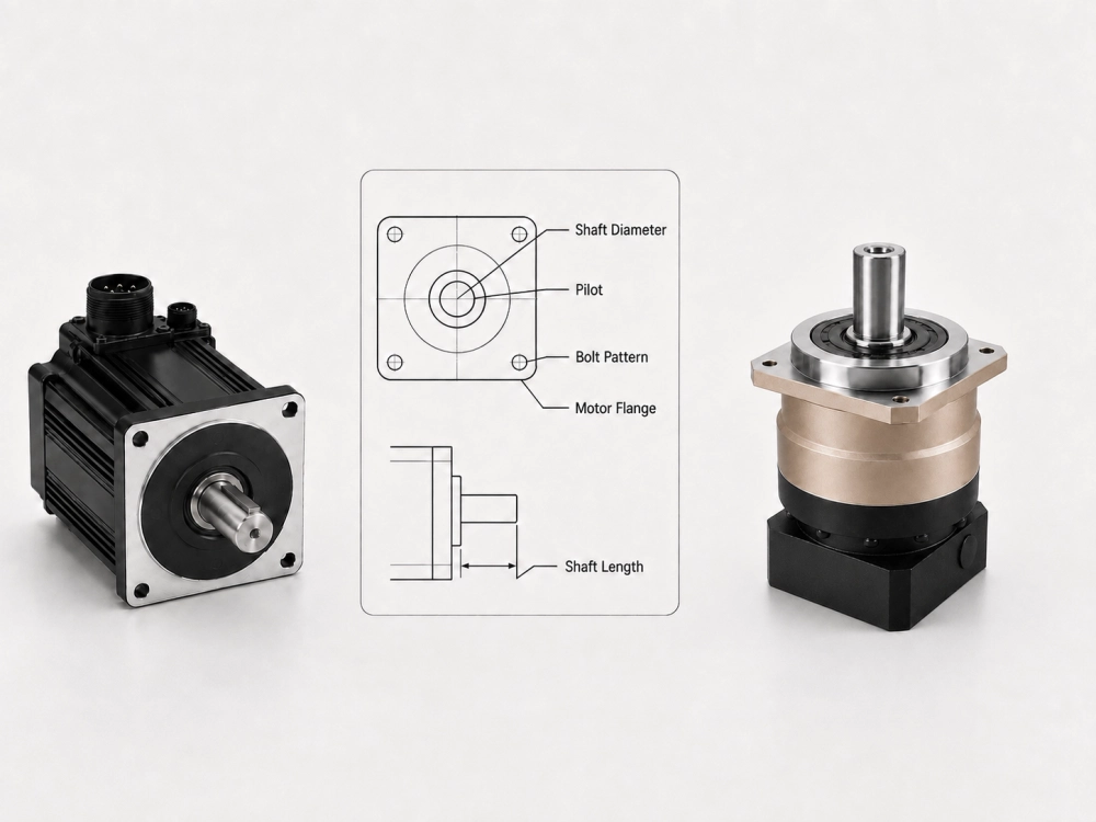
Verify the Motor Flange and Shaft Interface
Mechanical compatibility is one of the most common reasons an otherwise suitable reducer cannot be installed. Motors with the same power rating can use different flange dimensions and shaft sizes.
Before a supplier prepares the motor adapter and input coupling, provide:
- Motor manufacturer and exact model
- Motor flange outside dimensions
- Flange pilot diameter and pilot depth
- Bolt-hole quantity and size
- Bolt-circle diameter or hole spacing
- Motor shaft diameter
- Usable shaft length
- Keyway dimensions, if present
The flange pilot is particularly important because it locates the motor concentrically with the reducer. Mounting bolts secure the components, but they should not be expected to correct an inaccurate pilot fit.
If the motor and reducer axes are not correctly aligned, the drive may experience vibration, coupling stress, noise and premature input-bearing wear.
Keyed Shaft or Clamping Connection?
The motor shaft may connect to the reducer through a key, clamping hub or another manufacturer-specific coupling design.
Clamping connection
A properly designed clamping hub grips the motor shaft evenly. It is commonly used in precision servo gearbox assemblies because it can provide a rigid, concentric connection without introducing clearance from a loose key fit.
The clamping bore must match the actual motor shaft diameter. Using an incorrect sleeve or tightening method can reduce contact area and allow the shaft to slip under peak torque.
Keyed connection
A keyed shaft provides a positive mechanical drive and is widely used in industrial motor systems. The key width, key height, shaft diameter and usable shaft length must match the coupling design.
A key does not remove the need for accurate shaft alignment. Clearance between the shaft, key and hub can also influence noise and reversing performance.
The best connection depends on the motor, torque, speed and application. Do not modify the motor shaft or coupling without confirming how the change affects fit, balance and transmitted torque.
Check Motor and Load Inertia Without Repeating Servo Sizing
Inertia is especially relevant when a servo or stepper system must accelerate rapidly. The reducer changes the load inertia reflected back to the motor, helping the motor control a load that would otherwise be difficult to accelerate or stop.
However, ratio should not be selected only to obtain a favorable inertia relationship. A higher ratio also reduces output speed and changes the required motor operating range.
For the current gearbox for electric motor selection, provide the load inertia or enough machine information for it to be estimated, including:
- Rotating component dimensions and mass
- Linear moving mass
- Pulley, sprocket or ballscrew dimensions
- Required acceleration time
- Maximum cycle rate
Detailed servo tuning and inertia calculations belong to the complete motion-system design. The reducer supplier should at least understand the load type and acceleration cycle before confirming the model.
Check the Reducer Output Load
The output side of the reducer must support the forces created by the driven mechanism. A coupling, pulley, sprocket, pinion and output flange do not apply the same loads.
A belt or chain drive can create substantial radial force. The force increases when the pulley or sprocket is small or when belt tension is high. Mounting the load far from the reducer bearing also increases the bending moment on the output shaft.
Provide the supplier with:
- Output connection type
- Pulley, sprocket or pinion diameter
- Distance from the reducer face to the load center
- Direction of the radial force
- Expected axial force
- Whether the driven shaft has an external support bearing
An electric motor speed reducer may have sufficient torque capacity but insufficient bearing capacity for a heavily tensioned belt. Output torque and external load ratings must be checked separately.
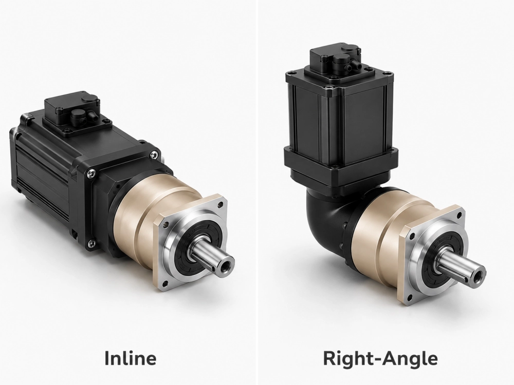
Choose Inline or Right-Angle Configuration
The machine layout determines whether the motor and reducer can be installed on one axis or need a 90-degree arrangement.
Inline planetary gearbox
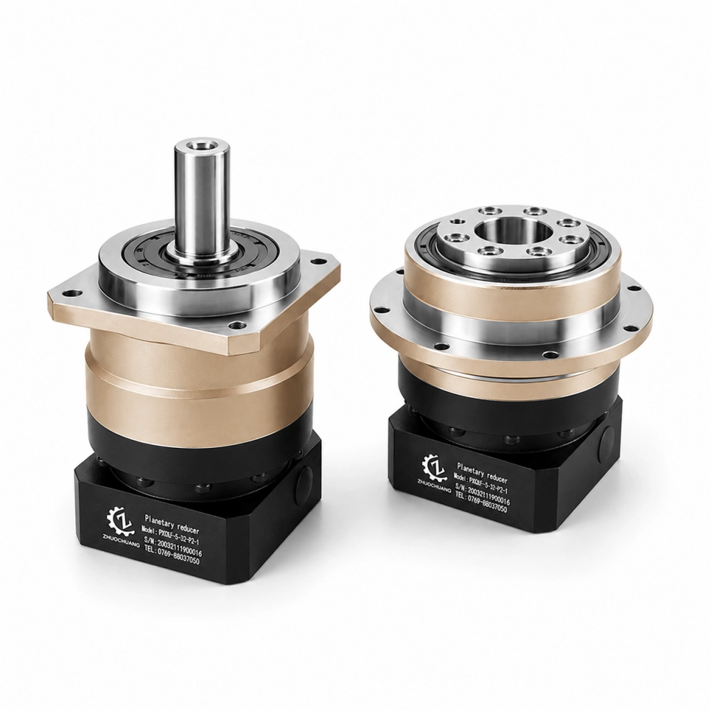
An inline gearbox keeps the motor, reducer and output shaft on the same centerline. It is suitable when the machine has enough axial space and requires a direct, compact transmission path.
Inline designs are commonly used in servo axes, ballscrew drives, rotary mechanisms and automated handling equipment.
Right-angle planetary gearbox
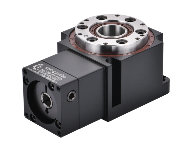
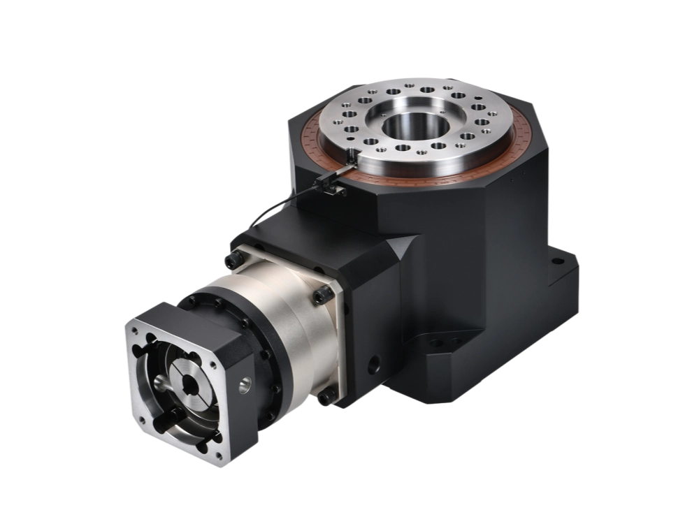
A right-angle planetary gearbox places the motor at 90 degrees to the output. It can reduce the total machine length and help the motor fit beside the driven mechanism.
The decision should be based on the complete installation envelope, cable direction, maintenance access and load position—not only on the reducer dimensions.
PlanetDrivePro supplies inline and right-angle precision planetary gearboxes that can be matched with different servo, stepper and BLDC motor interfaces.
When Is a Standard Industrial Gearmotor More Suitable?
A precision planetary reducer is not automatically the best choice for every electric motor. A standard industrial gearmotor may be more suitable when the application:
- Runs continuously in one direction
- Does not require accurate positioning
- Has generous installation space
- Uses a large AC induction motor
- Operates at a stable speed with limited acceleration
- Prioritizes low initial cost over compact precision
Large bulk conveyors, slow mixers and simple material-handling systems often use helical, bevel or worm gearmotors. By contrast, a planetary speed reducer for electric motor applications is more appropriate when the machine requires compact dimensions, controlled acceleration, frequent reversing, high torque density or precise positioning.
This distinction is important because selecting a precision reducer for the wrong application can increase cost without delivering a practical benefit.
Common Motor and Reducer Matching Errors
Providing motor power but not the motor model
Power does not define shaft diameter, flange pattern, pilot size or maximum speed. Always provide the exact motor model and dimensional drawing.
Selecting only by gear ratio
The correct ratio does not guarantee sufficient torque, input-speed capacity, bearing support or mechanical compatibility.
Using motor holding torque as operating torque
This is particularly risky with stepper motors. Available torque normally decreases as motor speed increases. Selection should use the torque available at the real operating speed.
Ignoring repeated acceleration torque
A torque peak that occurs every machine cycle is part of normal operation. It should not be treated as an occasional emergency load.
Assuming equal power means equal flange dimensions
Motors with the same rated power can have different body sizes, shafts and mounting patterns. Adapter design must use the actual drawing.
Using an unsuitable shaft sleeve
An inaccurate sleeve can create poor concentricity or insufficient clamping contact. The input coupling must be correctly sized for the motor shaft.
Ignoring output radial load
A small pulley or overhung sprocket can overload the reducer bearing even when output torque is within the rated range.
Choosing precision without defining the machine requirement
Backlash and stiffness should match the positioning task. Purchasing the lowest available backlash does not automatically improve a flexible or non-positioning machine.
Electric Motor Gear Reducer RFQ Checklist
The following information allows a supplier to evaluate the motor, reducer and load as one system.
| Selection item | Information to provide |
|---|---|
| Motor type | Servo, stepper, BLDC or another motor type |
| Motor identification | Manufacturer and complete model number |
| Motor performance | Rated power, rated speed, maximum speed and torque data |
| Required output | Normal speed, maximum speed and required ratio |
| Machine torque | Continuous, acceleration, reversing and emergency-stop torque |
| Motion cycle | Acceleration time, running time, stopping time and cycles per minute |
| Precision | Required backlash, repeatability or positioning accuracy |
| Motor interface | Flange, pilot, bolt holes, shaft and keyway dimensions |
| Output connection | Coupling, pulley, sprocket, pinion, ballscrew or flange |
| External load | Radial load, axial load and load application distance |
| Installation layout | Inline or right-angle arrangement and available space |
| Environment | Temperature, dust, moisture, vibration and cleanliness requirements |
| Supporting files | Motor drawing, machine layout, photographs and motion profile |
How PlanetDrivePro Supports Motor Interface Matching
PlanetDrivePro is the official international website of Dongguan Zhuochuang Precision Machinery Co., Ltd. We manufacture Zhuochuang inline and right-angle precision planetary gearboxes for industrial automation and motion-control applications.
Our team can evaluate an electric motor gear reducer requirement using the motor model and real machine conditions. The selection process can include:
- Ratio and operating-speed review
- Continuous and peak torque checks
- Motor shaft and flange matching
- Input adapter and coupling configuration
- Backlash and positioning requirements
- Output radial and axial loads
- Inline or right-angle installation
To request a recommendation, send the motor model, motor drawing, required output speed, load information, motion cycle and installation dimensions through our Contact or Request a Quote page.
Frequently Asked Questions
Can the same planetary gearbox fit different electric motors?
The reducer body may be suitable for several motors, but the input adapter, coupling bore and flange pattern must match the specific motor. Always confirm the complete motor model before ordering.
Can a planetary reducer be used with both servo and stepper motors?
Yes, provided the reducer’s speed, torque and interface match the motor and application. Servo and stepper systems have different operating characteristics, so the selection data should reflect the actual motor type.
What is the most important motor dimension for gearbox matching?
No single dimension is sufficient. The supplier normally needs the shaft diameter and length, flange dimensions, pilot diameter, bolt-hole pattern and keyway information.
Can an adapter plate connect any motor to any reducer?
No. An adapter can solve certain dimensional differences, but it cannot correct an unsuitable speed range, insufficient torque capacity, excessive motor shaft load or incompatible coupling design.
Is a keyed or clamping connection better?
Both can be reliable when correctly designed. Clamping connections are common in precision servo applications, while keyed connections are widely used in industrial drives. The choice depends on the motor shaft, speed, torque and reversing requirements.
How do I choose the ratio of an electric motor speed reducer?
Divide the expected motor operating speed by the required machine output speed. Then verify standard ratio availability, output torque, reducer input-speed limits and the complete motion cycle.
Does every electric motor need a precision planetary reducer?
No. Precision planetary reducers are most useful in compact, dynamic or positioning applications. A standard industrial gearmotor may be more economical for large, continuously rotating machinery that does not require controlled positioning.
What should I send when requesting a gearbox for electric motor matching?
Send the complete motor model and drawing, required output speed, continuous and peak torque, motion cycle, output connection, external load, installation dimensions and machine photographs.
Related Gearbox Guides
- How to Select a Gearbox for a Servo Motor – Review the specific dynamic, inertia and positioning requirements of servo-driven systems.
- Precision Planetary Gearbox Selection Guide – Understand how backlash, stiffness, torque capacity and bearings affect precision applications.
- 90 Degree Gear Reducer for Right-Angle Drives – Compare standard and precision right-angle layouts for space-limited machinery.
Conclusion
An electric motor gear reducer should be selected from the motor, reducer and machine requirements together. Begin by identifying whether the system uses a servo, stepper, BLDC or conventional industrial motor. Then confirm operating speed, continuous and peak torque, precision requirements, motor flange, shaft dimensions and output load.
The phrase speed reducer for electric motor covers a wide range of products, but precision planetary gearboxes are most valuable in compact automation systems that require controlled movement, frequent acceleration or reliable positioning. Supplying the complete motor model and machine data allows the reducer manufacturer to provide a mechanically compatible and technically appropriate solution.